HS50_advance_level 2.pdf - 第138页
07/2002 Editio n Student G uide HS -50 Advanc ed II 6 Cont rol & C ommun icatio n 8 T o be able t o use CAN as a indus trial field bus in an ope n system the CA N in Auto mation user’ s group CiA created a standard c…
Student Guide HS-50 Advanced II 07/2002 Edition
6 Control & Communication
7
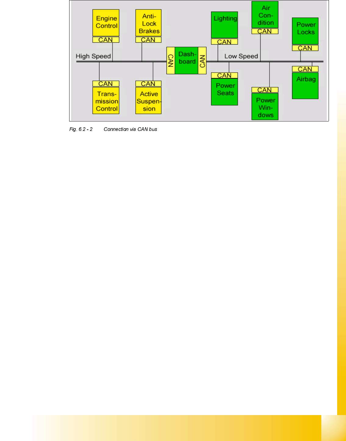
To improve the behavior of the vehicle even further, it was necessary for the different control sys-
tems (and their sensors) to exchange information. This was usually done by discrete interconnec-
tion of the different systems (i.e. point to point wiring). The requirement for information exchange
has then grown to such an extent that a cable network with a length of up to several miles and
many connectors was required. This produced growing problems concerning material cost, pro-
duction time and reliability.
The solution to this problem was the connection of the control systems via a serial bus system.
This bus had to fulfill some special requirements due to its usage in a vehicle. With the use of CAN,
point-to-point wiring is replaced by one serial bus connecting all control systems. This is accom-
plished by adding some CAN-specific hardware to each control unit that provides the "rules" or
protocol for transmitting and receiving information via the bus.
Due to the high volume production in the automotive and industrial markets, low cost protocol de-
vices are available.CAN is a multi-master bus with an open, linear structure with one logic bus line
and equal nodes. The number of nodes is not limited by the protocol. In the CAN protocol, the bus
nodes do not have a specific address. Instead, the address information is contained in the identi-
fiers of the transmitted messages, indicating the message content and the priority of the message.
The number of nodes may be changed dynamically without disturbing the communication of the
other nodes. Multicasting and Broadcasting is supported by CAN.
There is a high data transfer rate of 1000 kilobits per second at a maximum bus length of 40
meters or 130 feet when using a twisted wire pair which is the most common bus medium used
for CAN. Message length is short with a maximum of 8 data bytes per message and there is a low
latency between transmission request and start of transmission.
The bus access is handled via the advanced serial communications protocol Carrier Sense Mul-
tiple Access/Collision Detection with Non-Destructive Arbitration. This means that collision of
messages is avoided by bitwise arbitration without loss of time.
07/2002 Edition Student Guide HS-50 Advanced II
6 Control & Communication
8
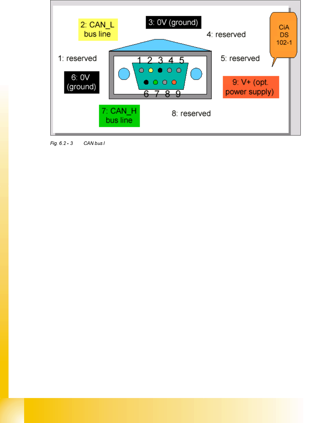
To be able to use CAN as a industrial field bus in an open system the CAN in Automation user’ s
group CiA created a standard called CiA DS 102-1 which is based on the 11898-standard. One
important issue in this standard is the proposal to use a 9-pole SUB-D connector for the connec-
tion of nodes to the CAN bus lines.
The bus signals CAN_H and CAN_L are available on pins 7 and 2. The other pins serve as power
or ground wires or are reserved for future extensions of the standard.
7KH&$1%XV6\VWHPLQWKH6,3/$&(0DFKLQH
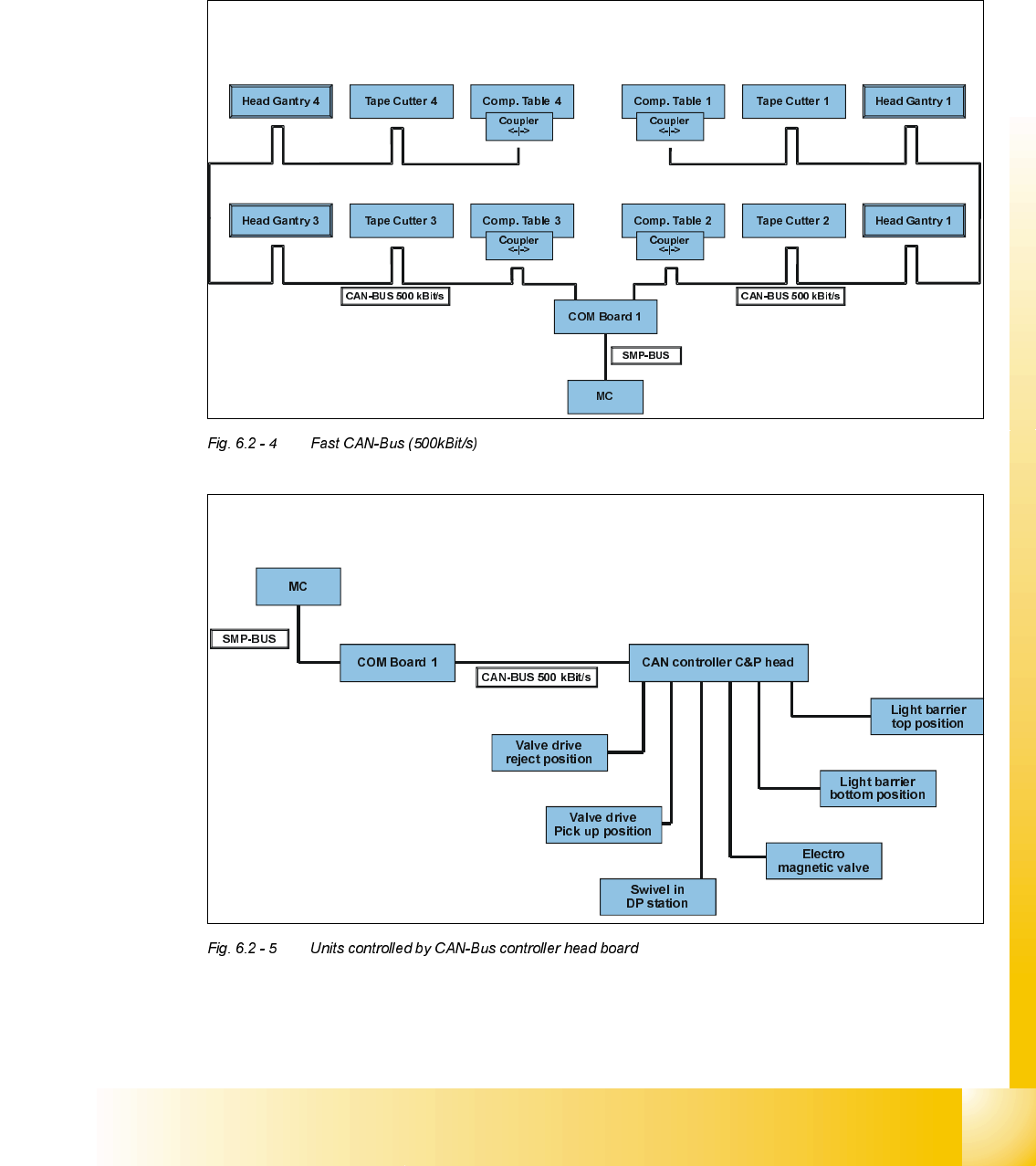
The CAN-Bus systems in the SIPLACE HS-50 series machine uses bit rates of 500 Kbit /sec (fast
CAN-Bus) and 125 Kbit /sec (slow CAN-Bus).
The fast CAN-Bus is used to control all tape cutters, component tables and all elements on the
collect & place head that are not axis specific. The slow CAN-Bus on the other side is used to con-
trol the conveyor functions and all I/O operations, see Fig. 6.3-1 and 6.3-2.
When errors occur with an element controlled on the CAN-Bus the error messages tend to be non
specific and often confusing. Here it is important to remember that when the machine controller
transmits a message to an element on the CAN-Bus it expects to receive an acknowledgement
that the message has been received. Often errors are displayed when the acknowledgement is
missing however the error often clears itself because the machine controller automatically retrans-
mits the message and then receives the acknowledgement. Only if the lack of acknowledgement
persists does the error become permanent.
When troubleshooting on the CAN-Bus system it is important to consider what element is being
controlled and what response is required. This can be quite difficult in the complex order of say
Student Guide HS-50 Advanced II 07/2002 Edition
6 Control & Communication
9
the pick up sequence. The easiest way to troubleshoot the system is to use the single functions
tests in the SITEST program to identify the element with the problem, before diagnosing the
source of the problem itself.
)DVW&$1%XV
!)DVW&$1%XVN%LWV
!8QLWVFRQWUROOHGE\&$1%XVFRQWUROOHUKHDGERDUG