HS50_advance_level 2.pdf - 第44页
1 - 6 Content s Student G uide H S-50 Advanc ed II 07/200 2 Edition 6

1 - 5
Student Guide HS-50 Advanced II Contents
07/2002 Edition
5
3.3.17.1 Tools and equipment . . . . . . . . . . . . . . . . . . . . . . . . . . . . . . . . . . . . . . . . . . . . . . 56
3.3.17.2 Parts. . . . . . . . . . . . . . . . . . . . . . . . . . . . . . . . . . . . . . . . . . . . . . . . . . . . . . . . . . . 57
3.3.17.3 Removing ELR1 or ELR2 . . . . . . . . . . . . . . . . . . . . . . . . . . . . . . . . . . . . . . . . . . . 57
3.3.17.4 Fitting ELR1 or ELR2 . . . . . . . . . . . . . . . . . . . . . . . . . . . . . . . . . . . . . . . . . . . . . . 57
3.3.18 Replacing electrolytic capacitor C1 (00342399-01). . . . . . . . . . . . . . . . . . . . . . . . . 58
3.3.18.1 Tools and equipment . . . . . . . . . . . . . . . . . . . . . . . . . . . . . . . . . . . . . . . . . . . . . . 58
3.3.18.2 Parts. . . . . . . . . . . . . . . . . . . . . . . . . . . . . . . . . . . . . . . . . . . . . . . . . . . . . . . . . . . 58
3.3.18.3 Removing the electrolytic capacitor . . . . . . . . . . . . . . . . . . . . . . . . . . . . . . . . . . . 58
3.3.18.4 Fitting the electrolytic capacitor . . . . . . . . . . . . . . . . . . . . . . . . . . . . . . . . . . . . . . 59
3.3.19 Replacing main power filter Z1 (00342397-01) . . . . . . . . . . . . . . . . . . . . . . . . . . . . 59
3.3.19.1 Tools and equipment . . . . . . . . . . . . . . . . . . . . . . . . . . . . . . . . . . . . . . . . . . . . . . 59
3.3.19.2 Parts. . . . . . . . . . . . . . . . . . . . . . . . . . . . . . . . . . . . . . . . . . . . . . . . . . . . . . . . . . . 60
3.3.19.3 Removing main power filter Z1. . . . . . . . . . . . . . . . . . . . . . . . . . . . . . . . . . . . . . . 60
3.3.19.4 Fitting the main power filter Z1 . . . . . . . . . . . . . . . . . . . . . . . . . . . . . . . . . . . . . . . 60
3.3.20 Replacing the inrush current limitation board (EST) (00341831-01). . . . . . . . . . . . 61
3.3.20.1 Tools and equipment . . . . . . . . . . . . . . . . . . . . . . . . . . . . . . . . . . . . . . . . . . . . . . 61
3.3.20.2 Parts. . . . . . . . . . . . . . . . . . . . . . . . . . . . . . . . . . . . . . . . . . . . . . . . . . . . . . . . . . . 61
3.3.20.3 Removing the EST board. . . . . . . . . . . . . . . . . . . . . . . . . . . . . . . . . . . . . . . . . . . 61
3.3.20.4 Fitting the EST board . . . . . . . . . . . . . . . . . . . . . . . . . . . . . . . . . . . . . . . . . . . . . . 62

1 - 6
Contents Student Guide HS-50 Advanced II
07/2002 Edition
6
Student Guide HS-50 Advanced II 07/2002 Edition
3 Power Supply
7
3RZHU6XSSO\
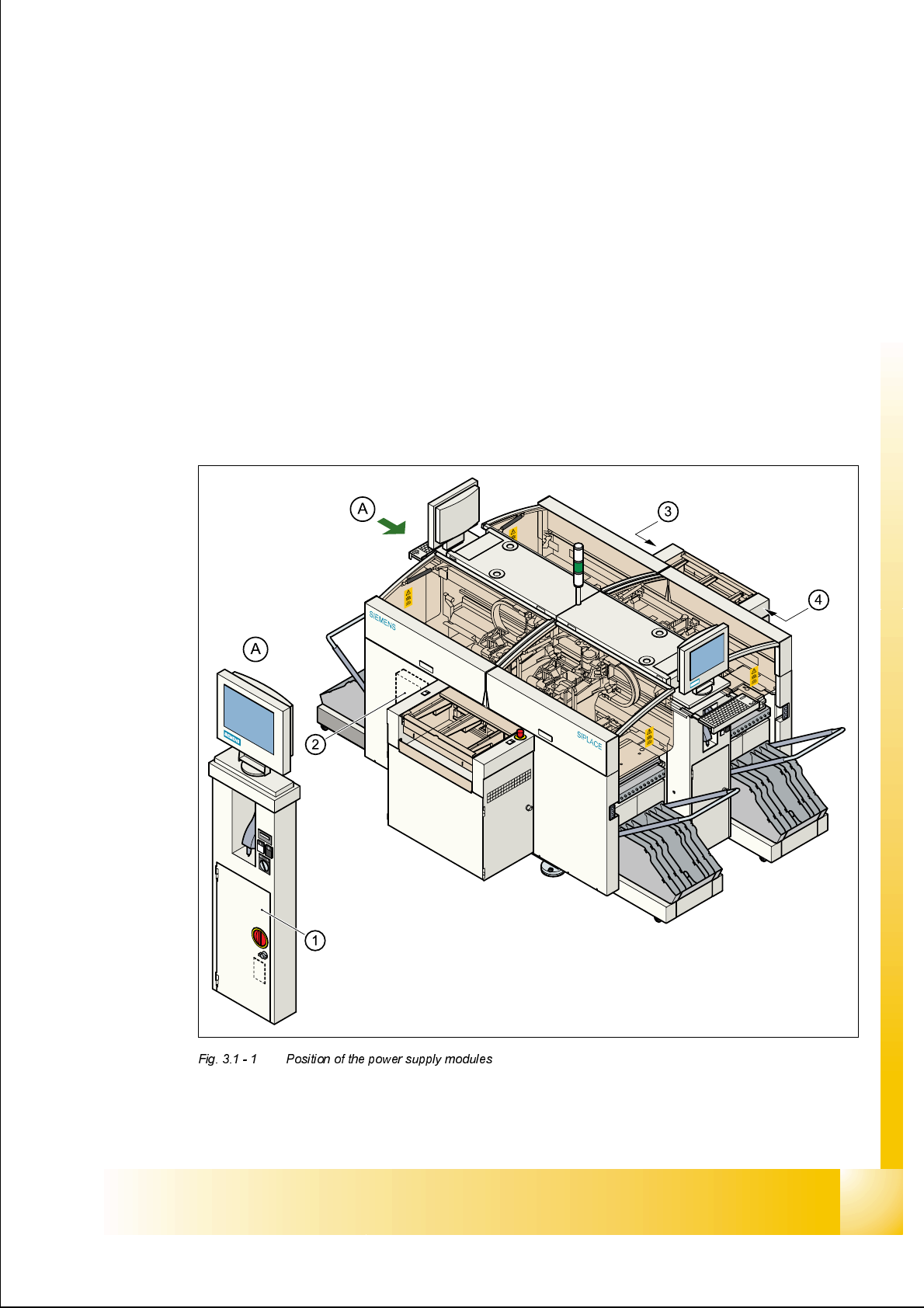
3RVLWLRQRIWKHSRZHUVXSSO\PRGXOHV
The diagram below shows the position of the modules that generate or distribute the power
needed to operate the placement system:
– Power supply unit (Pos. 1)
– Main distribution unit (Pos. 2)
– Control unit (Pos. 3)
– Servo unit (Pos. 4)