HS50_advance_level 2.pdf - 第62页
07/2002 Editio n Student G uide HS -50 Advanc ed II 3 Power Sup ply 24 PCC*) y axis x axis star ax is dp axi s z axis PCB conveyor PCB c lam ping Widt h adjustmen t PCB stopper Lif ting t able Used ta pe cutt er Active…

Student Guide HS-50 Advanced II 07/2002 Edition
3 Power Supply
23
– all four flaps over the push-buttons for raising and lowering the component changeover tables
must be closed.
– the minimum operating pressure must have been reached.
– the software enable must have been given, thus activating the safety circuit.
– the power supply must be sending 24 V to the Start buttons and the protective contactor com-
bination.
– If one of the Start buttons is now pressed, the protective contactor combination (PCC) will
switch and activate the following components:
– 200 V link voltage for the servo amplifier for the gantry axes
– 100 V link voltage for the star axes
– 230 V operating voltage for the lifting table motors
– the servo unit will receive a "Servo enable" signal for the servo amplifier
– 34 V operating voltage is switched to the component changeover tables
– 24 V operating voltage is switched to the used tape cutters.
The machine is now ready for service.
07/2002 Edition Student Guide HS-50 Advanced II
3 Power Supply
24
PCC*)
y axis
x axis
star axis
dp axis
z axis
PCB conveyor
PCB clamping
Width adjustment
PCB stopper
Lifting table
Used tape cutter
Active
Yes
Voltage
200V
200V
100V
30V
30V
Active
Yes
Yes
Yes
Yes
Yes
Yes
PCC*)
y axis
x axis
star axis
dp axis
z axis
PCB conveyor
PCB clamping
Width adjustment
PCB stopper
Lifting table
Used tape cutter
Active
No
Voltage
0V
0V
6V
30V
30V
Active
Yes
No
Yes
No
No
No
PCC*)
y axis
x axis
star axis
dp axis
z axis
PCB conveyor
PCB clamping
Width adjustment
PCB stopper
Lifting table
Used tape cutter
Active
No
Voltage
0V
0V
6V
30V
30V
Active
No
No
No
No
No
No
*) PCC Protective contactor combination
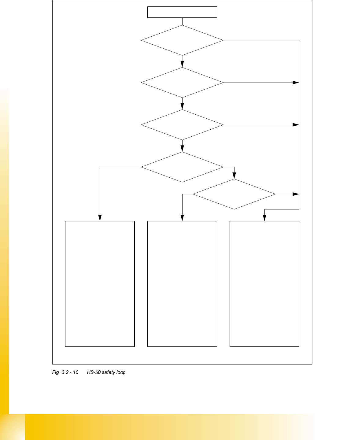
Startbutton pressed
Compressed air
min. 5.0 bar?
Emerg.stop button
pressed?
Component table safety
circuit interrupted?
Protective cover open?
Key switch
closed (position “I”)?
Yes No
YesNo
No
Yes
Yes
Yes
No
No
Student Guide HS-50 Advanced II 07/2002 Edition
3 Power Supply
25
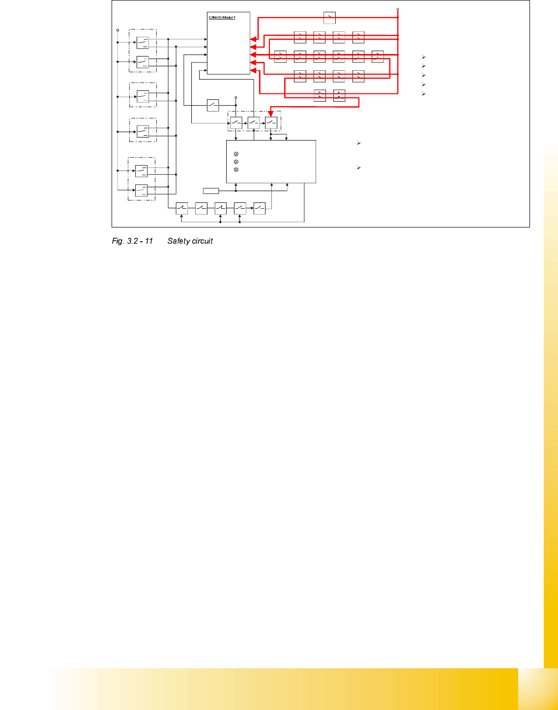
+24V
pressur sensor
E-stops
protective covers
component table
component flaps
SZ4
X3 (Input)
X4 (Input)
X7 (Input)
X8 (Input) X16 (Input)
X1 (Input)
X5 (Input)
X9 (Input)
X2 (Output)
+24V
Key
left side
Key
right side
Key
Key
Output
Conveyor
Start
Stop
Start
Stop
Start
Stop
Start
Stop
Key
Key
Intput
Conveyor
Start
Stop
Start
Stop
L+ X1 X3 X5
L- X2 X4 X6
X11 (Input)
+24V
SSK
Ctrl _ON
SZ4SZ3SZ2SZ1SZ23
Ready
GND
SZ23
Contro l_ON
X14
To be able to start the machine the
safety loop must be closed . The safety
loop consists of:
E-Stops
Component flaps
protective covers
component tables
pressure sensor
With the safety loop closed two functions are fullfilled :
Via the SLIO-module 1
and the
CAN-Bus all devices
are recognized and no error message is sent from the
machine controller to the station computer.
24V are also connected to the SSK giving the
permission to activate the machine software .