HS50_advance_level 2.pdf - 第318页
07/2002 Editio n Student G uide HS -50 Advanc ed II 10 Star Axis 14 .(<WRILJ TDS 120 A 2.5Z = Serv o board z -axis TDS 120 / 1D = Servo board dp - a xis TDS 120 = Pin con figurati on LED: Rea dy f…
Student Guide HS-50 Advanced II 07/2002 Edition
10 Star Axis
13
$[LVG\QDPLFV
NOTE:
All SITEST functions are explained by the use of gantry 1
7RROVDQG7HVW$LGV
– 2 or 4 channel storage oscilloscope.
– SIPLACE axis test box.
–SITEST software.
NOTE
The machine must have reached its operating temperature before you begin to adjust the axes.
Therefore, make sure to switch it on, at least 30 minutes before you begin to work.
6HUYR%RDUG+HDG$[HV+6
07/2002 Edition Student Guide HS-50 Advanced II
10 Star Axis
14
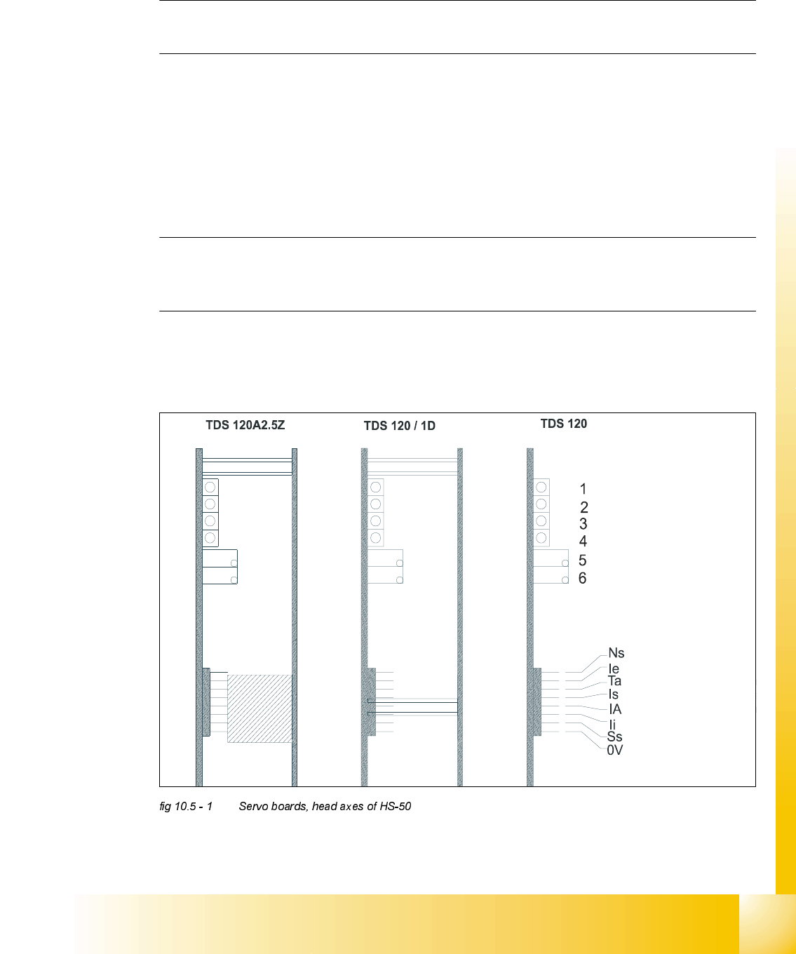
.(<WRILJ
TDS 120 A2.5Z = Servo board z-axis
TDS 120 / 1D = Servo board dp - axis
TDS 120 = Pin configuration
LED: Ready for operation
LED: Enable output stage
LED: Effective current limit
LED: Error
Potentiometer: Tacho
Potentiometer: P-Amplification
.(<
(1) LED: Ready for operation
(2) LED: Enable output stage
(3) LED: I
RMS
limit
(4) LED: Error
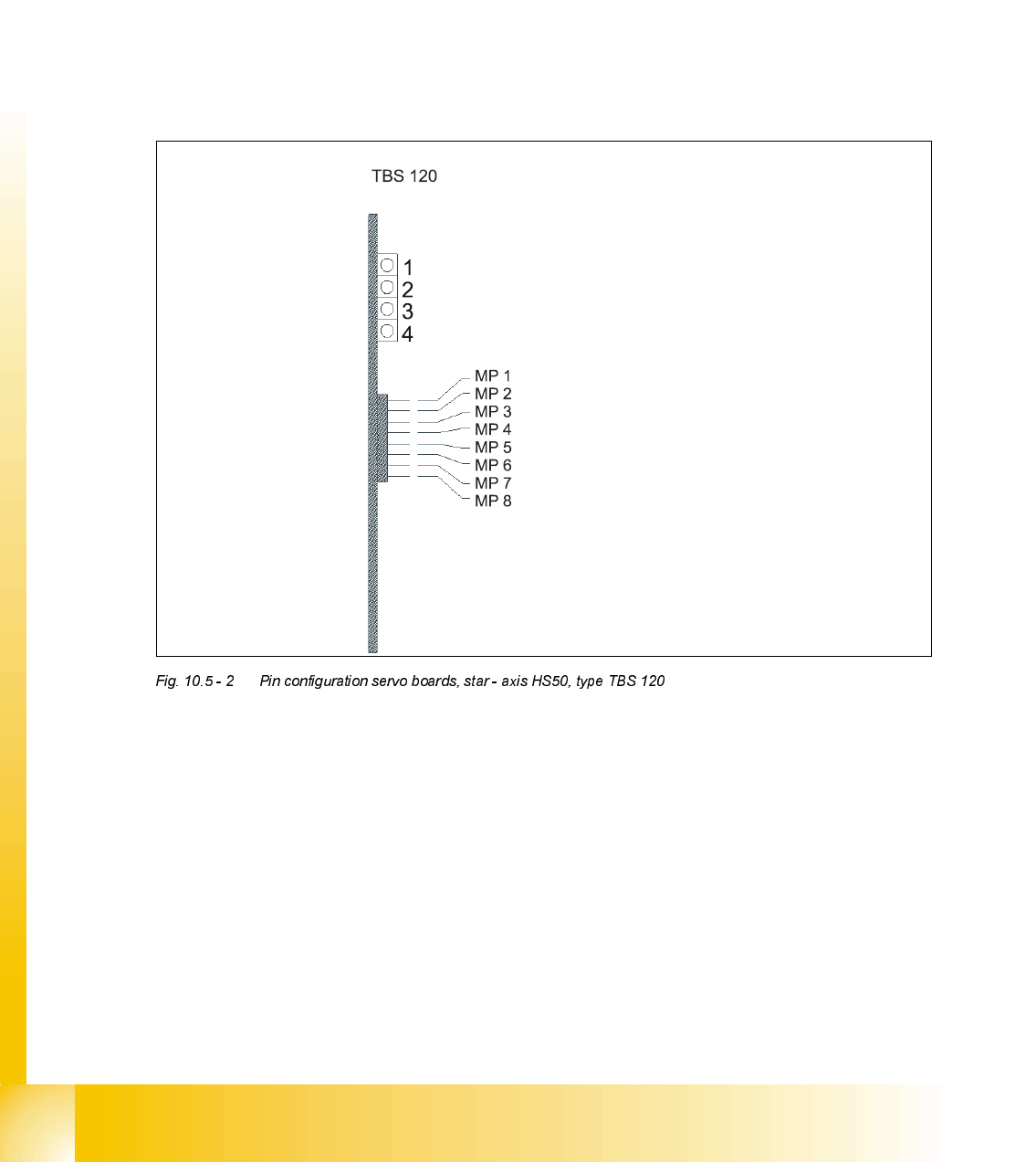
MP1 = Nominal current "I-S (U)"
MP2 = Nominal current "I-S (W)"
MP3 = Actual current "I-ist (U)"
MP4 = Actual current "I-ist (W)"
Ns Speed setpoint value
Ie Setpoint value, power input
Ta Tacho (real tacho voltage)
Is Nominal current (speed controller output)
IA Motor manipulated variable
(speed controller output)
li Actual current
Ss Sensor stop signal
0V Amplifier electronic GND
MP5 = "U-nominal (U)"
MP6 = "U-nominal (W)"
MP7 = Free
MP8 = Reference potential "0V"
Student Guide HS-50 Advanced II 07/2002 Edition
10 Star Axis
15
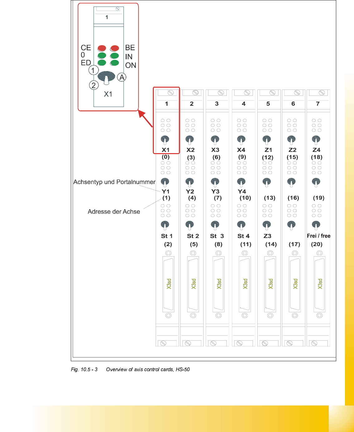
2YHUYLHZRI$[HV&RQWURO&DUGV+6
type of axis and gantry number
adress of axis
'3 '3
'3
'3
CE = Counting error
0 = Zero pulse
ED = End signal
BE = General error, module error
IN = Initialized
ON = Servo ON
(A) Axis enable switch
(1) Servo ON
(2) Servo OFF