HS50_advance_level 2.pdf - 第276页
07/2002 Editio n Student G uide HS -50 Advanc ed II 9 Z-Axis 16 $ GMXVWPHQWRI0HFK DQLFDO3RVLWLRQRI9 DOYH'ULY HV ➠ Set the motor pos ition of th e valve d rives "Pic k-up / P lacement " and &quo…
Student Guide HS-50 Advanced II 07/2002 Edition
9 Z-Axis
15
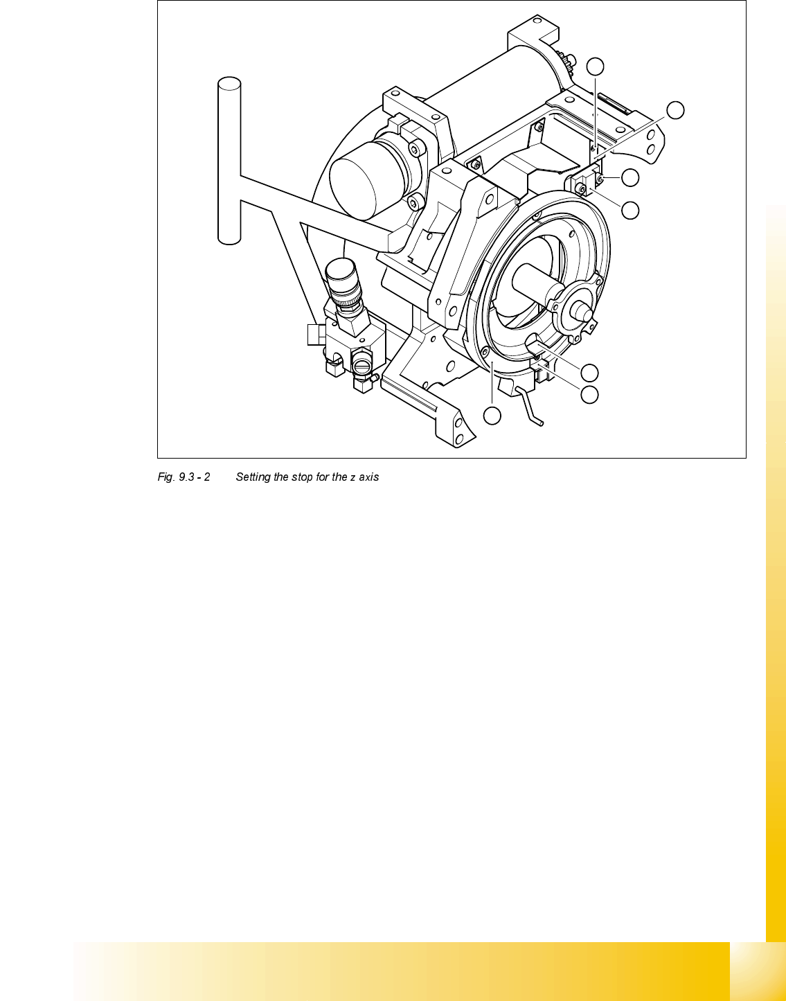
.H\
(1) M2x4 hexagon socket-head screw
(2) Stop piece
(3) 2 x M2.5x8 hexagon socket-head screw
(4) Stop
(5) Snap jaws of the z axis
(6) Raceway
(A) Insert the z axis gauge here
6
A
5
4
3
2
1
07/2002 Edition Student Guide HS-50 Advanced II
9 Z-Axis
16
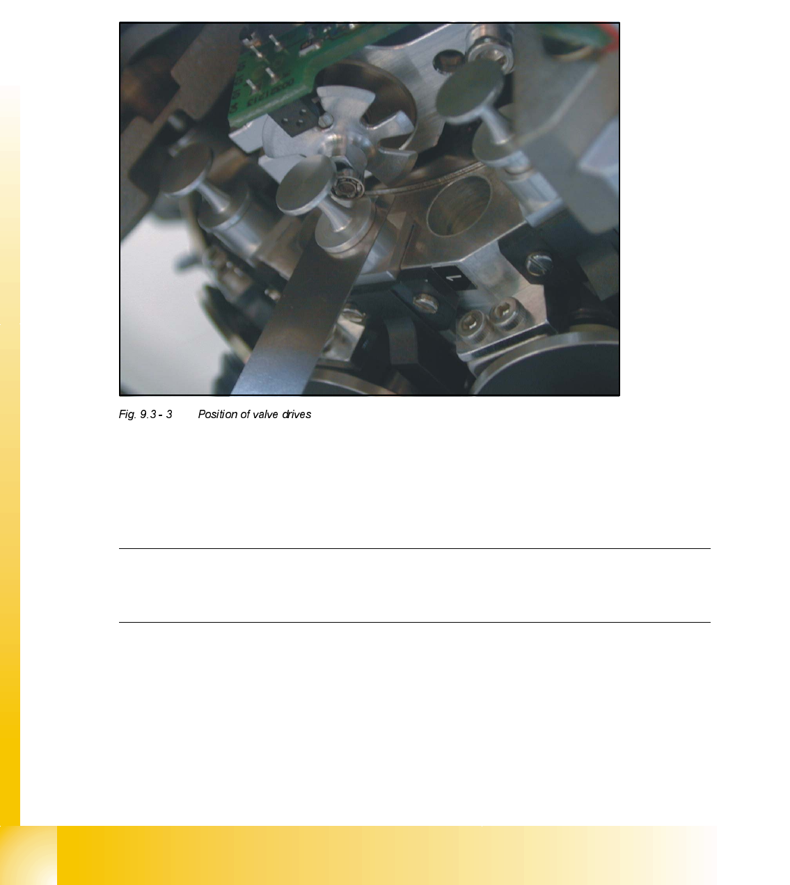
$GMXVWPHQWRI0HFKDQLFDO3RVLWLRQRI9DOYH'ULYHV
➠
Set the motor position of the valve drives "Pick-up / Placement" and "Ejection" according to the
figure below.
➠ Insert the distance gauge between valve plunger and valve casing.
➠ Turn the valve drive to 90° degrees, opposite to its initial position.
2WKHU0HFKDQLFDO$GMXVWPHQWVRQWKH6WDU
➠
Insert the blast air transition tubes so that they will protrude 0.5 mm from the surface of the
circular arc guide.
NOTE
The blast air tubes at the valve plungers should be at a distance of 0.2 mm from the encoder
of the dp - axis.
Student Guide HS-50 Advanced II 07/2002 Edition
9 Z-Axis
17
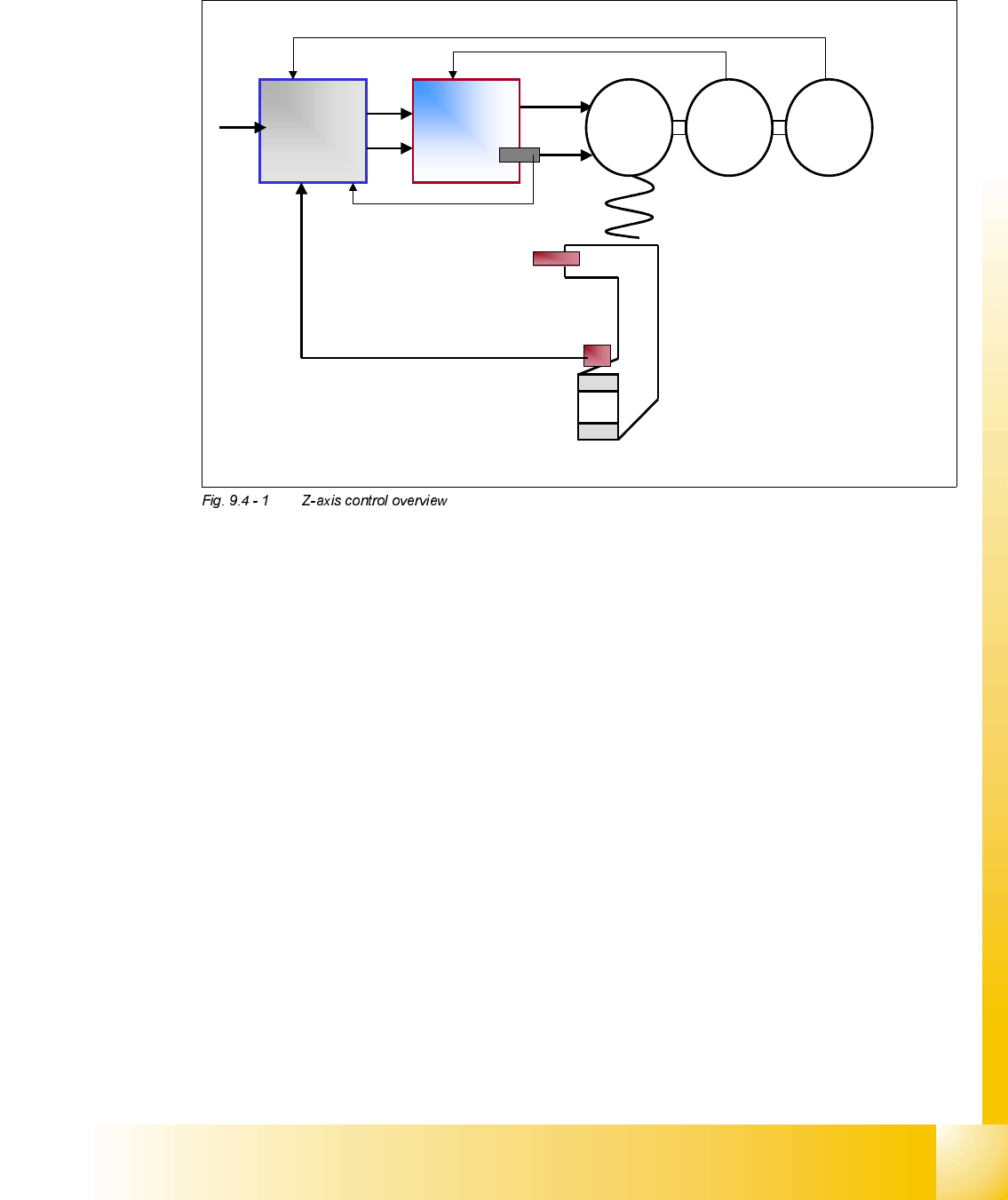
=D[LVFRQWURORYHUYLHZ
Here we can see that the basic elements of the Z axis control system are the same as the other
axis we have studied. The DC control system consisting of an Axis Controller, Servo Amplifier, Mo-
tor and track signals remains the same.
The primary difference if the way the Z axis ’End Signal’ is generated. On the diagram we can
clearly see that the Z axis ’Light barrier bottom’ is used to generate this signal in most cases. Only
when larger placement forces are required is the other control method used where the ’End Signal’
is generated by the ’Current Sensor’ on the Servo card. More details on the subject are given later
in the section ’Z axis Modes’.
The remaining element shown in the diagram is the ’Light barrier up’ this is used to control various
items and more detail is given on the timing diagrams shown in the following section.
To get the end signal very
quickly we use the light
barrier bottom signal.
Axis
controller
Servo
amplifier
M
=
G
=
Rotor
position
encoder
Light barrier up
End signal with
Light barrier
bottom
End signal from
current sensor
We define higher placement
forces with end signal triggered
by current sensor signal.