HS50_advance_level 2.pdf - 第353页
S tudent Guide HS-50 Adva nced II Editio n 07/200 2 12 S pecial handlin g for th e Z-axis 9 7 UDYHOSU RILOHRI WKH= D[LV =D[LV WUDY HOSURILO HGRZ QZDU GVRQSL FNXS 0RGH Normal downwa rd mo tio…
Student Guide HS-50 Advanced II
12 Special handling for the Z-axis Edition 07/2002
8
(DUO\YDFXXP
This function switches the vacuum on after exiting from the upper light barrier to ensure that the
best vacuum possible has been created in the nozzle.
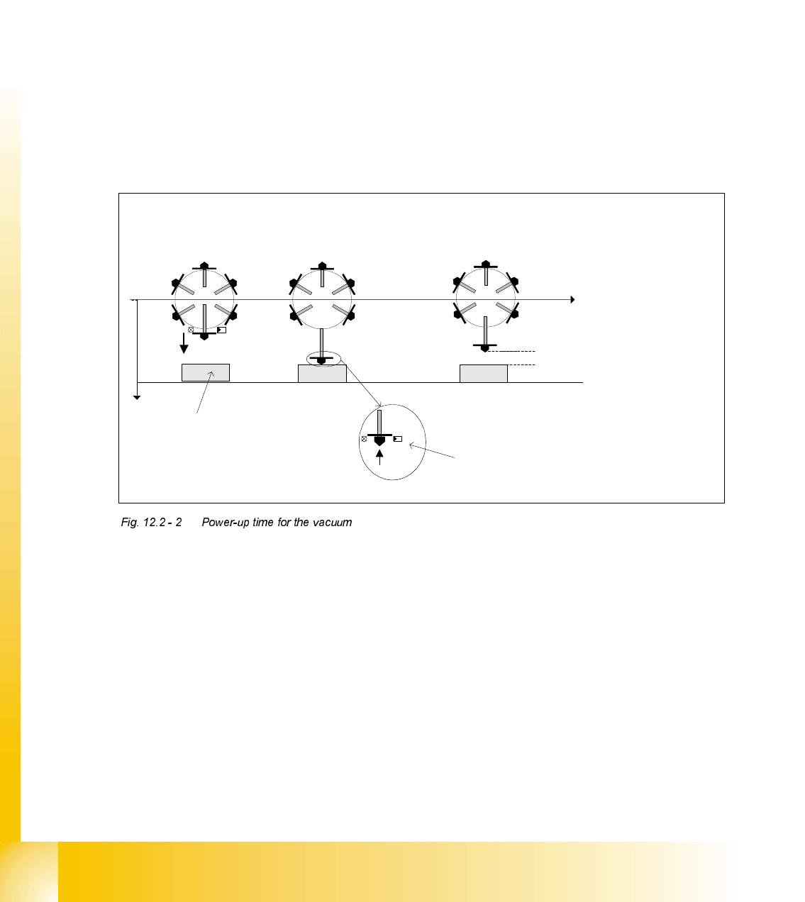
3RZHUXSWLPHIRUWKHYDFXXP
The following power-up times for the vacuum can be defined individually for each package form:
1. Vacuum with light barrier: The vacuum is switched on just like before when "Light barrier at
bottom" is enabled. This corresponds to the Z-axis travel profile downwards mode 1.
2. Early vacuum: When the "Early vacuum" function is activated, the vacuum is switched on when
exiting from the upper light barrier.
3. MC switches on vacuum: The vacuum is switched on by the MC by the "Pick-up without
contact" function once the Z position has been reached.
3LFNXSZLWKRXWFRQWDFW
Pick-up without contact was specially implemented for 0201-type components to minimize pick-
up errors.
Components (of type 0201, for example) can be picked up without making contact. The nozzle is
positioned a specific distance ("height clearance") over the component to do this. The component
is then drawn up to the nozzle with the help of the vacuum created (and switched on by the MC).
The height clearance (distance between the component and the nozzle) is stored in the machine
database. The same height clearance applies to all components for contact-free pick-up.
Early vacuum:
Z-axis head, upper light
barrier is activated
Vacuum:
Lower light barrier is
activated
Vacuum MC:
Z-axis has reached bottom position ->
MC issues the command to switch on the
vacuum
Height clearance
t
Pick-up at height
clearance level
Pick-up
z
Light
barrier
at top
Light barrier at bottom
Component
Student Guide HS-50 Advanced II
Edition 07/2002 12 Special handling for the Z-axis
9
7UDYHOSURILOHRIWKH=D[LV
=D[LVWUDYHOSURILOHGRZQZDUGVRQSLFNXS
0RGHNormal downward motion with light barrier at bottom
0RGHCalibration mode for pick-up without contact
=D[LVWUDYHOSURILOHXSZDUGVRQSLFNXS
0RGHStandard mode
0RGHCreep mode, i.e. the Z-axis moves up slowly the first few millimeters.
0RGHCreep mode, i.e. the Z-axis moves up slowly the first two millimeters.
The figure shows the travel profile for the Z-axis when moving upwards. Using the parameters
V
Start
and S
Start
, a creep path can be set up in the acceleration phase, and with the parameters
V
End
and S
End
in the deceleration phase.
Spring travel
approx.
200 µm
Height
clearance
Pick-up position
Pick-up position
with height
clearance
Pick-up at height
clearance level
Normal pick-up
with light barrier
z
400 µm
200 µm
600 µm
800 µm
1000 µm
1200 µm
1400 µm
1600 µm
1800 µm
Component
Spring travel
approx.
200 µm
Height
clearance
Pick-up position
Pick-up position
with height
clearance
Pick-up at height
clearance level
Normal pick-up
with light barrier
z
400 µm
200 µm
600 µm
800 µm
1000 µm
1200 µm
1400 µm
1600 µm
1800 µm
Component
Z-axis
s
[µm]
v
[m/s]
Acceleration phase Deceleration phase
Creep path
s
Start
V
Start
Creep path
s
End
V
End
V
End
V
Start
Student Guide HS-50 Advanced II
12 Special handling for the Z-axis Edition 07/2002
10
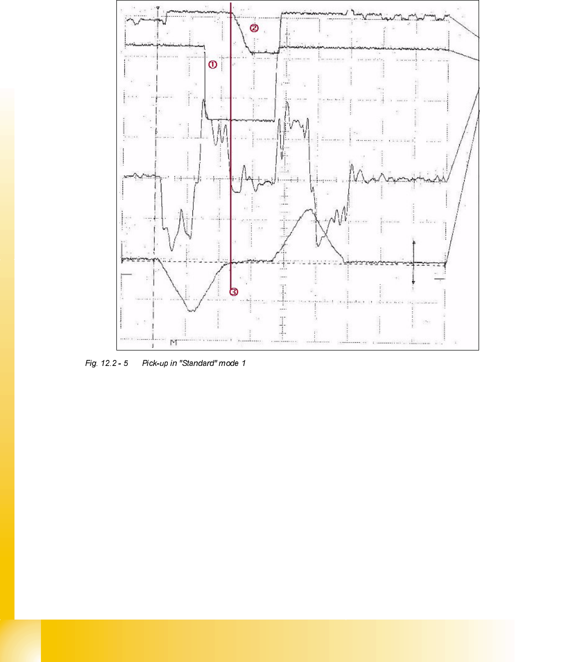
7UDYHOSURILOHVLQGHWDLO
3LFNLQJXSDFRPSRQHQWLQ6WDQGDUGPRGH
6LJQDOVIURPWRSWRERWWRP
Positional deviation: 1V 10 ms
Force signal: 5 V 10 ms
Iactual: 5 V 10 ms
Vtarget: 5 V 10 ms
The acceleration for the Z-axis is reduced here to 98.2%. The result is that the “special mode 44
digits slow” is not switched on.
Reduction of force after braking has begun in order to pick up the component from the feeder
securely and without damaging it.
From 6 to 8 digits are printed on the component so that the nozzle lands properly on the
component.
End signal for " Downwards"