HS50_advance_level 2.pdf - 第180页
07/2002 Editio n Student G uide HS -50 Advanc ed II 7 X-Axis 22 (1) M4 x 35 hexagon s ocket-he ad scre w (2) T ensioni ng key (3) Sy nchroni zing dis k, long (4) O penin g in te nsion ja ck for tooth ed belt (5) Y -axis …

Student Guide HS-50 Advanced II 07/2002 Edition
7 X-Axis
21
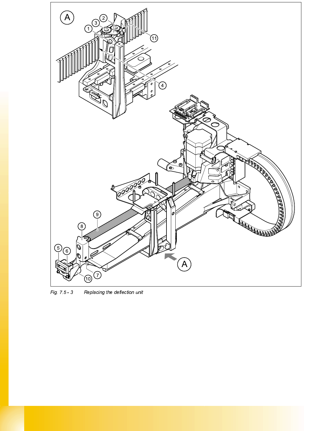
5HPRYLQJWKHGHIOHFWLRQXQLW
➠ Switch the placement system off and secure it to prevent switching on again.
➠ To slacken the toothed belt (item 9 in Fig. 7.5 - 3)
– loosen the locknut (item 11 in Fig. 7.5 - 3
) and
– turn the hexagon socket-head screw counter-clockwise (item 1 in Fig. 7.5 - 3
).
➠ Remove the M4 x 35 hexagon socket-head screw (item 1 in Fig. 7.5 - 3).
➠ Remove the tensioning key (item 2 in Fig. 7.5 - 3) from the synchronizing disk (item 3 in Fig.
7.5 - 3
).
➠ Pull the toothed belt (item 9 in Fig. 7.5 - 3) out through the opening in the tension jack (item 4
in Fig. 7.5 - 3
).
➠ Unthread the toothed belt from the deflection unit (item 8 in Fig. 7.5 - 3).
➠ Loosen the two M3 x 8 hexagon socket-head screws (item 6 in Fig. 7.5 - 3) and remove the y
brake ’external’ (item 5 in Fig. 7.5 - 3
).
➠ Loosen the two M6 x 10 hexagon socket-head screws (item 7 in Fig. 7.5 - 3) and remove the
deflection unit ’X’ (item 8 in Fig. 7.5 - 3
).
➠ Remove the elastomeric spring (item 10 in Fig. 7.5 - 3) from the deflection unit.
07/2002 Edition Student Guide HS-50 Advanced II
7 X-Axis
22
(1) M4 x 35 hexagon socket-head screw (2) Tensioning key
(3) Synchronizing disk, long (4) Opening in tension jack for toothed belt
(5) Y-axis brake, external (6) 2 x M3 x 8 hexagon socket-head screws
(7) 2 x M6 x 10 hexagon socket-head screws (8) Deflection unit - X
(9) Synchroflex toothed belt (10) 25 x 10.5 x 50 elastomeric spring
(11) Locknut
Student Guide HS-50 Advanced II 07/2002 Edition
7 X-Axis
23
,QVWDOOLQJWKHGHIOHFWLRQXQLW¶;
➠ Fit the elastomeric spring (item 10 in Fig. 7.5 - 3) on the new deflection unit (item 8 in Fig.
7.5 - 3
).
➠ Use the two M6 x 10 hexagon socket-head screws (item 7 in Fig. 7.5 - 3) to fix the deflection
unit (item 8 in Fig. 7.5 - 3
) to the gantry.
➠ Align the ’external’ brake (item 5 in Fig. 7.5 - 3) so that it is parallel with the braking surface and
fix to the deflection unit (item 8 in Fig. 7.5 - 3
) using the two M3 x 8 hexagon socket-head
screws.
➠ Place the toothed belt (item 9 in Fig. 7.5 - 3) around the synchronizing disk of the deflection
unit (item 8 in Fig. 7.5 - 3
).
PLEASE NOTE
See Fig. 7.5 - 4, page 7 - 24 onward, for the following assembly steps.
➠ Feed the toothed belt into the opening (item 3 in Fig. 7.5 - 4) in the tension jack (item 2 in Fig.
7.5 - 4
) so that it runs approximately 270° around the ’long’ synchronizing disk (item 4 in Fig.
7.5 - 4
).
➠ Place the tensioning key (item 5 in Fig. 7.5 - 4) on the synchronizing disk (item 4 in Fig.
7.5 - 4
).
➠ Use a size 8 Allen key to turn the synchronizing disk (item 4 in Fig. 7.5 - 4) clockwise.
➠ Screw the hexagon socket-head screw (item 7 in Fig. 7.5 - 4) into the threaded hole in the
spacer bolt (item 6 in Fig. 7.5 - 4
) and pre-tension the X-axis toothed belt.
6HWWLQJV
➠ Push the head mount (item 1 in Fig. 7.5 - 4) towards X-axis motor unit as far as the stop on the
elastomeric spring.
➠ Turn the hexagon socket-head screw (item 7 in Fig. 7.5 - 4) to set the belt tension to 53 Hz +
1/-3 Hz.
CAUTION
Do not overstretch the toothed belt when adjusting the belt tension.
➠ Secure the hexagon socket-head screw (item 7 in Fig. 7.5 - 4) with the locknut (item 8 in Fig.
7.5 - 4
).