HS50_advance_level 2.pdf - 第179页
Stud ent Gu ide HS-5 0 Adva nced II 07/2 002 Ed ition 7 X- Axis 21 5HPRYL QJWKHGH IOHFWL RQXQLW ➠ Switch t he plac ement system off and secur e it to pr event s witchin g on aga in. ➠ T o slacken the tooth ed…

07/2002 Edition Student Guide HS-50 Advanced II
7 X-Axis
20
,QVWDOOLQJWKHWHQVLRQLQJNH\V
,QVWDOOLQJWKHWHQVLRQLQJNH\LWHP V\QFKURQL]LQJGLVNVKRUW
➠ Place the tensioning key on the ’short’ synchronizing disk (item 9 in Fig. 7.5 - 2).
➠ Use the M4 x 5 hexagon socket-head screw (item 8 in Fig. 7.5 - 2) to fix the tensioning key.
,QVWDOOLQJWKHWHQVLRQLQJNH\LWHPV\QFKURQL]LQJGLVNORQJ
➠ Fit the spacer bolt with the Benzing U-clip (item 7 in Fig. 7.5 - 2) on the new tensioning key.
➠ Place the tensioning key on the ’long’ synchronizing disk (item 10 in Fig. 7.5 - 2).
➠ Use the size 8 Allen key to turn the synchronizing disk slightly until the hexagon socket-head
screw (item 3 in Fig. 7.5 - 2
) can be screwed in.
➠ Pre-tension the toothed belt by turning the hexagon socket-head screw clockwise.
6HWWLQJV
➠ Push the head mount towards the X-axis motor as far as the stop on the elastomeric spring.
➠ Turn the hexagon socket-head screw to set the belt tension to 53 Hz + 1/-3 Hz.
CAUTION
Do not overstretch the toothed belt when adjusting the belt tension.
➠ Secure the hexagon socket-head screw (item 3 in Fig. 7.5 - 2) with the locknut (item 11 in Fig.
7.5 - 2
).
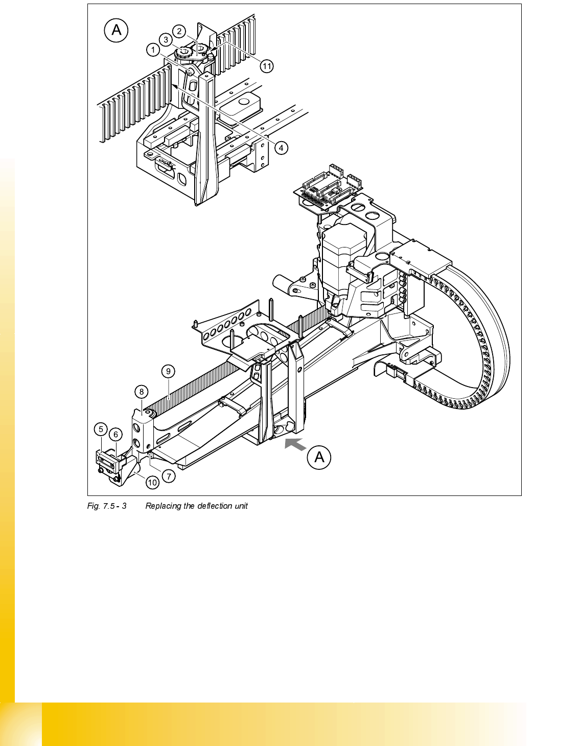
5HSODFLQJWKHGHIOHFWLRQXQLW
7RROVDQGHTXLSPHQW
– Set of DIN 911 Allen keys
– TSM belt tension measuring device, from item number 00326015-01
– "Measuring belt tensions" operating instructions
3DUWV
Deflection unit X, from item number 00330938-01

Student Guide HS-50 Advanced II 07/2002 Edition
7 X-Axis
21
5HPRYLQJWKHGHIOHFWLRQXQLW
➠ Switch the placement system off and secure it to prevent switching on again.
➠ To slacken the toothed belt (item 9 in Fig. 7.5 - 3)
– loosen the locknut (item 11 in Fig. 7.5 - 3
) and
– turn the hexagon socket-head screw counter-clockwise (item 1 in Fig. 7.5 - 3
).
➠ Remove the M4 x 35 hexagon socket-head screw (item 1 in Fig. 7.5 - 3).
➠ Remove the tensioning key (item 2 in Fig. 7.5 - 3) from the synchronizing disk (item 3 in Fig.
7.5 - 3
).
➠ Pull the toothed belt (item 9 in Fig. 7.5 - 3) out through the opening in the tension jack (item 4
in Fig. 7.5 - 3
).
➠ Unthread the toothed belt from the deflection unit (item 8 in Fig. 7.5 - 3).
➠ Loosen the two M3 x 8 hexagon socket-head screws (item 6 in Fig. 7.5 - 3) and remove the y
brake ’external’ (item 5 in Fig. 7.5 - 3
).
➠ Loosen the two M6 x 10 hexagon socket-head screws (item 7 in Fig. 7.5 - 3) and remove the
deflection unit ’X’ (item 8 in Fig. 7.5 - 3
).
➠ Remove the elastomeric spring (item 10 in Fig. 7.5 - 3) from the deflection unit.
07/2002 Edition Student Guide HS-50 Advanced II
7 X-Axis
22
(1) M4 x 35 hexagon socket-head screw (2) Tensioning key
(3) Synchronizing disk, long (4) Opening in tension jack for toothed belt
(5) Y-axis brake, external (6) 2 x M3 x 8 hexagon socket-head screws
(7) 2 x M6 x 10 hexagon socket-head screws (8) Deflection unit - X
(9) Synchroflex toothed belt (10) 25 x 10.5 x 50 elastomeric spring
(11) Locknut