HS50_advance_level 2.pdf - 第170页
07/2002 Editio n Student G uide HS -50 Advanc ed II 7 X-Axis 12 The PCB centeri ng and p ick-u p positio n detec tion com ponents fo r the fe eder mod ules are mounted on the unde rside o f the head m ount. (1) Three…
Student Guide HS-50 Advanced II 07/2002 Edition
7 X-Axis
11
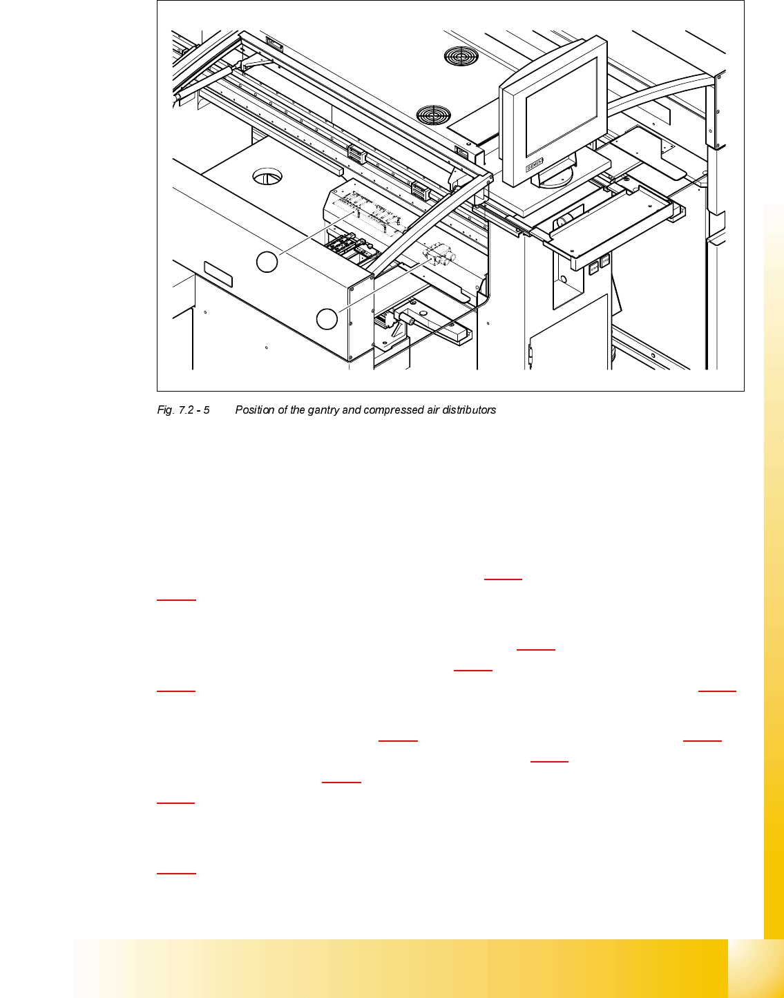
(1) Gantry distributor
(2) Compressed air distributor
The other three ribbon cables supply power and transmit control signals for the gantry axis drives.
They connect the gantry distributor (see item 1 in Fig. 7.2 - 5
) to the X/Y distributor (item 2 in Fig.
7.2 - 4
).
The gantry is supplied with compressed air via seven compressed air hoses. The lines are con-
nected to the compressed air distributor (see item 2 in Fig. 7.2 - 5
). They run in the trailing cable
and end at the inlet couplings (see item 7 in Fig. 7.2 - 4
) on the motor bracket (see item 9 in Fig.
7.2 - 4
). Seven compressed air lines continue from the outlet couplings (see item 8 in Fig. 7.2 - 4)
to the collect&place head.
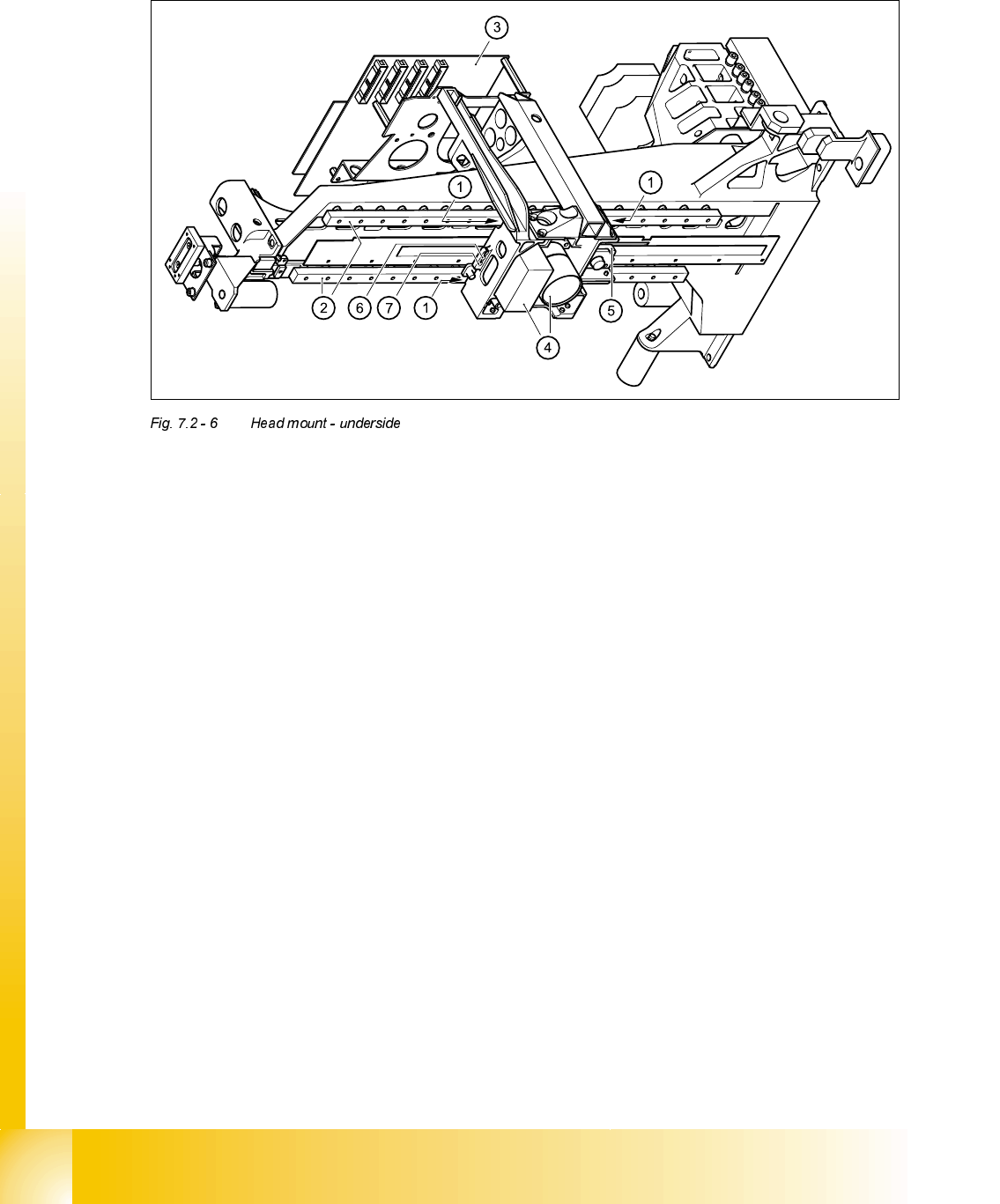
The X-axis motor (see item 5 in Fig. 7.2 - 4
) moves the head mount (see item 4 in Fig. 7.2 - 4) in
the x direction with the aid of a toothed belt (see item 6 in Fig. 7.2 - 4
). The mount is fixed to three
shuttles (see item 1 in Fig. 7.2 - 6
) on the two recirculating ball screw units (see item 2 in Fig.
7.2 - 6
) on the underside of the gantry. This layout guarantees that movement of the X-axis is both
precise and generates very little friction.
The head mount supports the collect&place head /DLM1 and the head board (see item 3 in Fig.
7.2 - 6
).
1
2
07/2002 Edition Student Guide HS-50 Advanced II
7 X-Axis
12
The PCB centering and pick-up position detection components for the feeder modules are
mounted on the underside of the head mount.
(1) Three shuttles on the two recirculating ball screw units
(2) Recirculating ball screw units
(3) Head board
(4) Camera beneath the gantry for PCB centering and pick-up position detection for the feeder
modules
(5) Incremental encoder for the X-axis scale
(6) End position proximity switch 2
(7) End position proximity switch 1 and reference point for the X-axis
Student Guide HS-50 Advanced II 07/2002 Edition
7 X-Axis
13
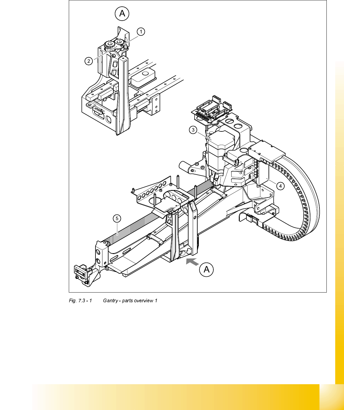
3DUWVRYHUYLHZ
(1) Tensioning key (00329478-01) (2) Tensioning key (00329485-01)
(3) X-axis motor unit (00333167-02) (4) Linear motor, primary part (00333148-01)
(5) Toothed belt, Synchroflex 50ATS5/1205, E9/11 (00331076-01)