HS50_advance_level 2.pdf - 第68页
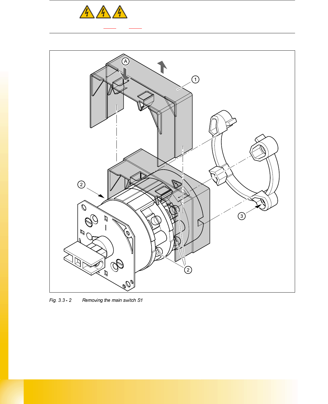
07/2002 Editio n Student G uide HS -50 Advanc ed II 3 Power Sup ply 30 5HPRYLQJ WKHPDLQ VZLWFK DANGER Switch off the place ment syste m and d isconne ct from the po wer supply ( see sections 3.3.1 and 3.3.2 )…
Student Guide HS-50 Advanced II 07/2002 Edition
3 Power Supply
29
:KDWWRGRRQFRPSOHWLRQRIWKHVHUYLFLQJZRUN
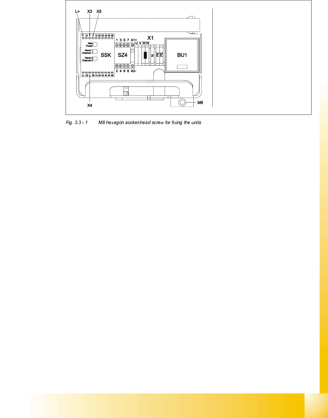
➠ Fit the power supply unit and fix in place with the M8 hexagon socket-head screw
➠ Make sure that you do not squash the cable when inserting the board
➠ Lock the safety doors
➠ Remove the key and keep in a safe place
5HSODFLQJWKHPDLQVZLWFK6
7RROVDQGHTXLSPHQW
– Set of slotted-head screwdrivers
– Set of DIN 911 Allen keys
– Digital multimeter
– Self-adhesive labels
– HS-50 detailed circuit diagrams
3DUWV
32C4/3-pole/40A main switch, item number 00342395-01
Carefully remove the unit
Make sure that the cable does
not get caught up
Be careful not to damage the
insulation
07/2002 Edition Student Guide HS-50 Advanced II
3 Power Supply
30
5HPRYLQJWKHPDLQVZLWFK
DANGER Switch off the placement system and disconnect from the power
supply (see sections 3.3.1 and 3.3.2).
➠ Use the screwdriver to bend back the lug (A) of the touch guard (1) slightly and then pull the
guard up and off.
➠ Loosen and remove the cable clamping screws (2) one by one and identify with adhesive la-
bels.
,QSXW 2XWSXW
Cable colour brown black

Student Guide HS-50 Advanced II 07/2002 Edition
3 Power Supply
31
➠ Loosen the M5 hexagon socket-head screws (3) and remove the switch.
)LWWLQJWKHPDLQVZLWFK
➠ Fix the main switch in place using M5 hexagon socket-head screws (3).
➠ Reconnect the labelled cables.
➠ Use the digital voltmeter to measure the voltages at terminals L1, L2, L3 or T1, T2 and T3.
➠ Switch off the placement system and disconnect from the power supply (see sections 3.3.1 and
3.3.2
).
➠ Replace the touch guard (item 1 in Fig. 3.3 - 2 on page 3 - 30) over the main switch.
➠ Complete the servicing work as described in section 3.3.3 on page 3 - 29.
5HSODFLQJWKHPRWRUWULSEORFN06$
7RROVDQGHTXLSPHQW
– Set of slotted-head screwdrivers
– Digital multimeter
– HS-50 detailed circuit diagrams
3DUWV
5HPRYLQJWKHPRWRUWULSEORFN
DANGER Switch off the placement system and disconnect from the power
supply (see sections 3.3.1 and 3.3.2).
'HVLJQDWLRQ ,WHPQXPEHU
Motor trip block ZM-16-PKZ2 00342495-01
for 3 x 380 VAC / 3 x 400 VAC / 3 x 415 VAC main power connection
Motor trip block ZM-32-PKZ2 00342496-01
for 3 x 204 VAC for USA / 3 x 230 VAC