HS50_advance_level 2.pdf - 第70页
07/2002 Editio n Student G uide HS -50 Advanc ed II 3 Power Sup ply 32 T urn th e swit ch (1) counte r-clock wise to positi on "0" Fold down the safety flap (2 )

Student Guide HS-50 Advanced II 07/2002 Edition
3 Power Supply
31
➠ Loosen the M5 hexagon socket-head screws (3) and remove the switch.
)LWWLQJWKHPDLQVZLWFK
➠ Fix the main switch in place using M5 hexagon socket-head screws (3).
➠ Reconnect the labelled cables.
➠ Use the digital voltmeter to measure the voltages at terminals L1, L2, L3 or T1, T2 and T3.
➠ Switch off the placement system and disconnect from the power supply (see sections 3.3.1 and
3.3.2
).
➠ Replace the touch guard (item 1 in Fig. 3.3 - 2 on page 3 - 30) over the main switch.
➠ Complete the servicing work as described in section 3.3.3 on page 3 - 29.
5HSODFLQJWKHPRWRUWULSEORFN06$
7RROVDQGHTXLSPHQW
– Set of slotted-head screwdrivers
– Digital multimeter
– HS-50 detailed circuit diagrams
3DUWV
5HPRYLQJWKHPRWRUWULSEORFN
DANGER Switch off the placement system and disconnect from the power
supply (see sections 3.3.1 and 3.3.2).
'HVLJQDWLRQ ,WHPQXPEHU
Motor trip block ZM-16-PKZ2 00342495-01
for 3 x 380 VAC / 3 x 400 VAC / 3 x 415 VAC main power connection
Motor trip block ZM-32-PKZ2 00342496-01
for 3 x 204 VAC for USA / 3 x 230 VAC
07/2002 Edition Student Guide HS-50 Advanced II
3 Power Supply
32
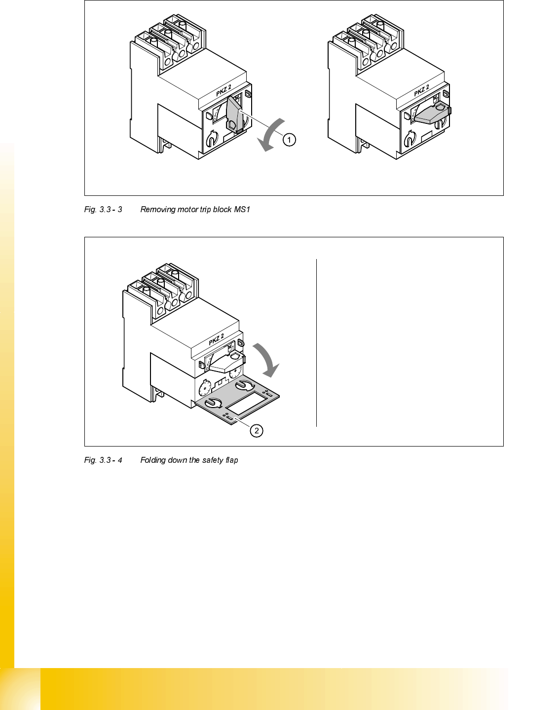
Turn the switch (1) counter-clockwise to position "0"
Fold down the safety flap (2)
Student Guide HS-50 Advanced II 07/2002 Edition
3 Power Supply
33
)LWWLQJWKHPRWRUWULSEORFN
➠ Check the type of motor trip block before inserting it. The type is dependent on the operating
voltage.
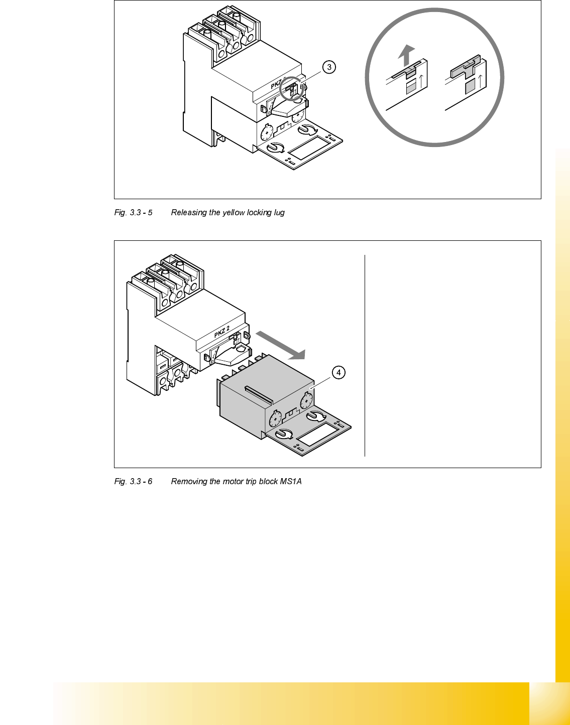
Use the screwdriver to push the yellow locking lug (3) upwards
Remove the motor trip block (4)
0DLQSRZHUYROWDJHV 7\SH
415 VAC ± 5 % ZM-16-PKZ2
400 VAC ± 5 % ZM-16-PKZ2
380 VAC ± 5 % ZM-16-PKZ2
230 VAC ± 5 % ZM-32-PKZ2
204 VAC ± 5 % ZM-32-PKZ2