00196378-0102_UM X-Feeder_EN.pdf - 第62页
Operating Tape Feeder Modules Using the Operator Panel Overview of the Operator Panels 62 User Manual X Feeder Modules SIPLACE Family 4.3 Using the Operator Panel 4.3.1 Overview of the Operator Panels 4.3.1.1 Overview of…
Operating Tape Feeder Modules
Removing the Tape Setting Up the Feeder Module
User Manual X Feeder Modules SIPLACE Family 61
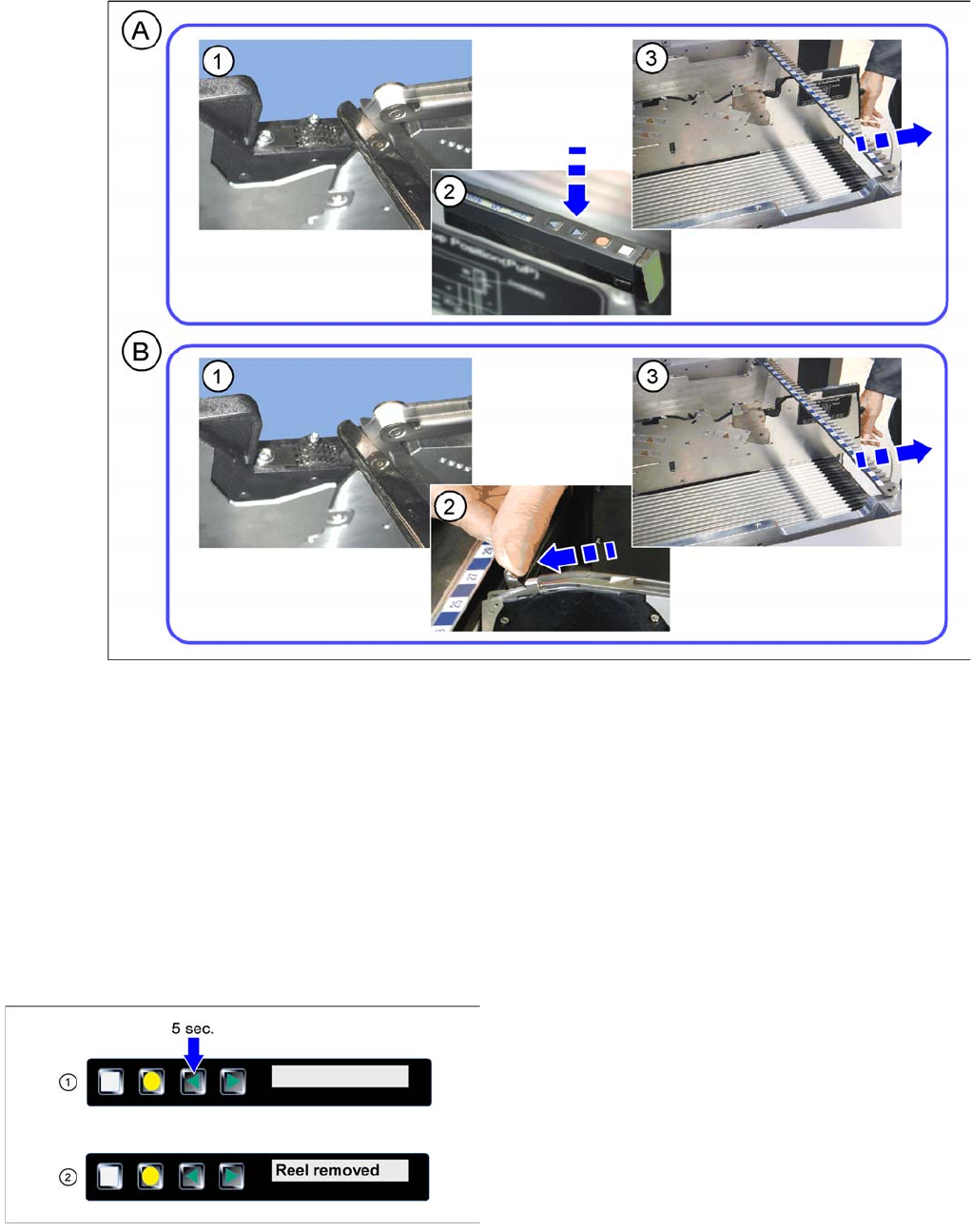
4.2.7.2 Removing the Tape on 8 -88 mm Feeder Modules
Removing the tape
A - Removal of tape with energy supply
►(1) Cut off the cover foil at the foil removal slot.
►(2) Press the "Backwards" key. The tape is moved out of the toothed wheel and lies free.
►(3) Pull the tape backwards out of the feeder module.
B - Removal of tape without energy supply
►(1) Cut off the cover foil at the foil removal slot.
►(2) Press the lever forwards until the stop.
►(3) Pull the tape backwards out of the feeder module.
Tearing down the feeder module
►(1) Press the Backwards button for at least 5
seconds.
►(2) After a successful tear down the display issues the
message Reel removed torn down.
Operating Tape Feeder Modules
Using the Operator Panel Overview of the Operator Panels
62 User Manual X Feeder Modules SIPLACE Family
4.3 Using the Operator Panel
4.3.1 Overview of the Operator Panels
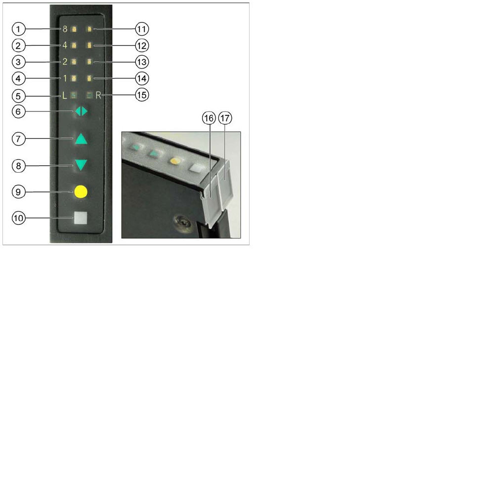
4.3.1.1 Overview of the Operator Panel for 2x8 mm Feeder Modules
Colors of the status display
The status display uses different colors to indicate the current state of the feeder module.
1. LED 8 mm pitch left track
2. LED 4 mm pitch left track
3. LED 2 mm pitch left track
4. LED 1 mm pitch left track
5. LED L left track active
6. Track change button
7. Forwards button
8. Backwards button
9. Foil button
10. Set button
11. LED 8 mm pitch right track
12. LED 4 mm pitch right track
13. LED 2 mm pitch right track
14. LED 1 mm pitch right track
15. LED R right track active
16. Status display left track
17. Status display right track
Display Meaning
Is off The feeder is not in use.
Lights up green The feeder module is used and ready-to-operate.
* The feeder module is set up with the correct components.
Lights up red Error
The feeder module was deactivated by the station.
Lights up orange Usually indicates a warning (see also "5.1 Messages for 2x8 mm Feeder Mod-
ules" [ ➙ 79])
* The feeder module immediately needs more components.
* This information is only displayed if the line is equipped with a SIPLACE setup verification software.
Operating Tape Feeder Modules
Adjusting the Pickup Positions Using the Operator Panel
User Manual X Feeder Modules SIPLACE Family 63
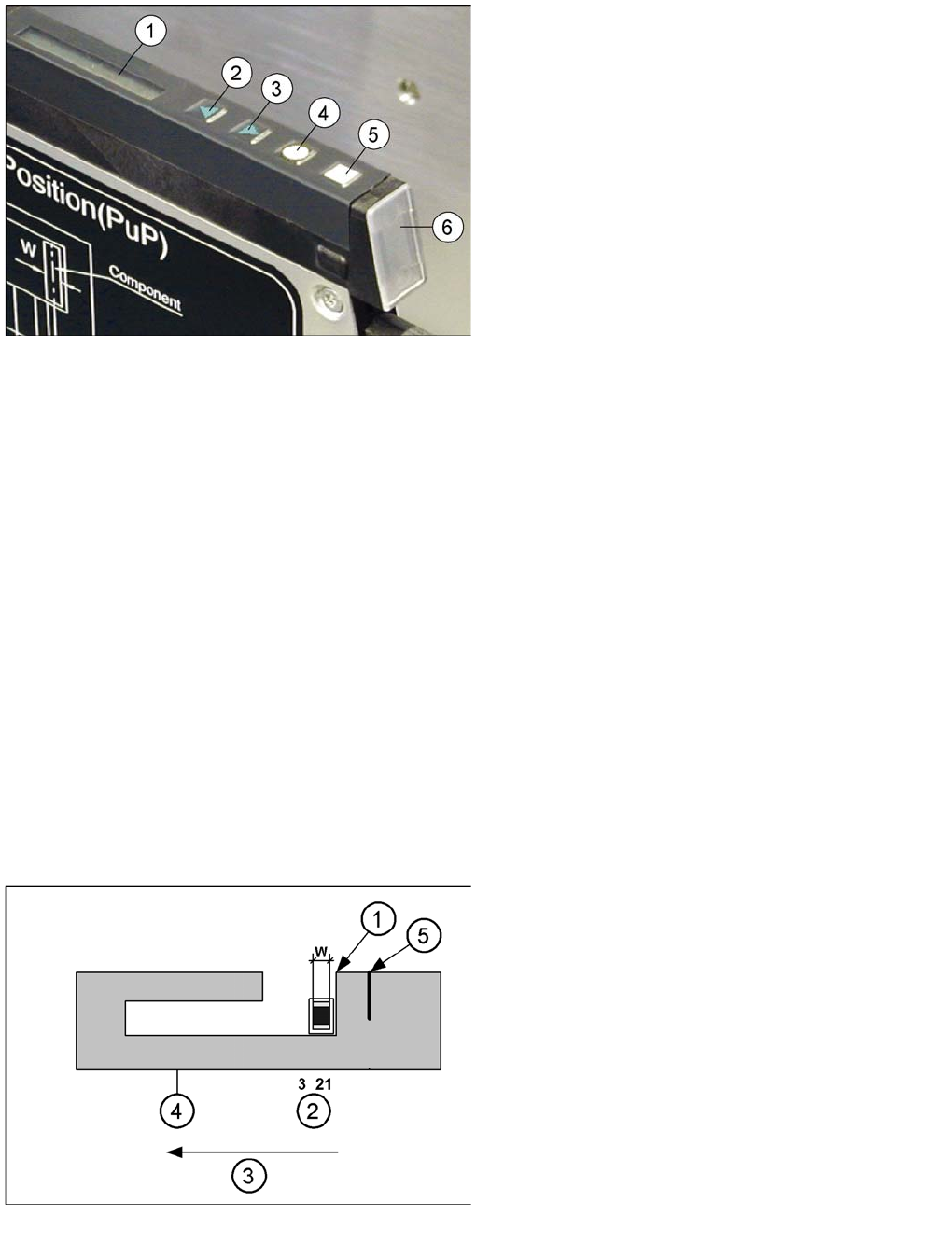
4.3.1.2 Overview of the Operator Panel for 8 - 88 mm Feeder Modules
Colors of the status display
The status display uses different colors to indicate the current state of the feeder module.
4.3.2 Adjusting the Pickup Positions
You adjust the pickup position of an X feeder module using the operator panel at its rear end.
4.3.2.1 Pick-Up Positions for 2x8 mm Feeder Modules
Three different pickup positions can be set for 2x8 mm feeder modules.
The 2x8 mm X feeder module has three pickup positions. These are marked on the pickup window by
three lines level with the sprocket wheel.
Legend
1. Display
2. Backwards button (green)
3. Forwards button (green)
4. Foil button (yellow)
5. Set button (white)
6. Status display
Display Meaning
Is off The feeder is not in use.
Lights up green The feeder module is used and ready-to-operate
(* and set-up with the correct components).
Lights up red Error - The feeder module was deactivated by the station.
Lights up orange Usually indicates a warning (see also "5.2 Messages for 8 - 88 mm Feeder Mod-
ules" [ ➙ 84])
* The feeder module immediately needs more components.
* Is only displayed if the line is equipped with a SIPLACE setup verification software.
Pickup positions for 2x8 mm X feeder modules
Legend
1. Removal edge
2. Pickup position
3. Direction of tape movement
4. Pickup window
5. 2nd removal edge for CSPs (Chip Scaled Package)
This removal edge ensures that the components do
not keep sticking.
W: Component width