00196378-0102_UM X-Feeder_EN.pdf - 第64页
Operating Tape Feeder Modules Using the Operator Panel Adjusting the Pickup Positions 64 User Manual X Feeder Modules SIPLACE Family The pickup position to be adjuste d depends on the comp onent wid th W: ▪ Pickup positi…
Operating Tape Feeder Modules
Adjusting the Pickup Positions Using the Operator Panel
User Manual X Feeder Modules SIPLACE Family 63
4.3.1.2 Overview of the Operator Panel for 8 - 88 mm Feeder Modules
Colors of the status display
The status display uses different colors to indicate the current state of the feeder module.
4.3.2 Adjusting the Pickup Positions
You adjust the pickup position of an X feeder module using the operator panel at its rear end.
4.3.2.1 Pick-Up Positions for 2x8 mm Feeder Modules
Three different pickup positions can be set for 2x8 mm feeder modules.
The 2x8 mm X feeder module has three pickup positions. These are marked on the pickup window by
three lines level with the sprocket wheel.
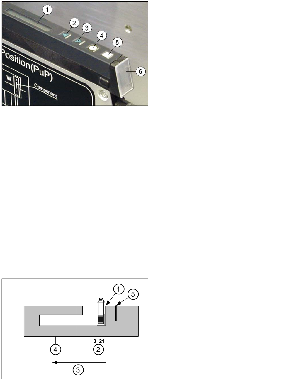
Legend
1. Display
2. Backwards button (green)
3. Forwards button (green)
4. Foil button (yellow)
5. Set button (white)
6. Status display
Display Meaning
Is off The feeder is not in use.
Lights up green The feeder module is used and ready-to-operate
(* and set-up with the correct components).
Lights up red Error - The feeder module was deactivated by the station.
Lights up orange Usually indicates a warning (see also "5.2 Messages for 8 - 88 mm Feeder Mod-
ules" [ ➙ 84])
* The feeder module immediately needs more components.
* Is only displayed if the line is equipped with a SIPLACE setup verification software.
Pickup positions for 2x8 mm X feeder modules
Legend
1. Removal edge
2. Pickup position
3. Direction of tape movement
4. Pickup window
5. 2nd removal edge for CSPs (Chip Scaled Package)
This removal edge ensures that the components do
not keep sticking.
W: Component width
Operating Tape Feeder Modules
Using the Operator Panel Adjusting the Pickup Positions
64 User Manual X Feeder Modules SIPLACE Family
The pickup position to be adjusted depends on the component width W:
▪ Pickup position 1: W <= 0.5 mm
▪ Pickup position 2: 0.5 mm < W <= 1.5 mm
▪ Pickup position 3: 1.5 mm < W <= 3.5 mm
The set pickup position can be changed as follows:
NOTICE
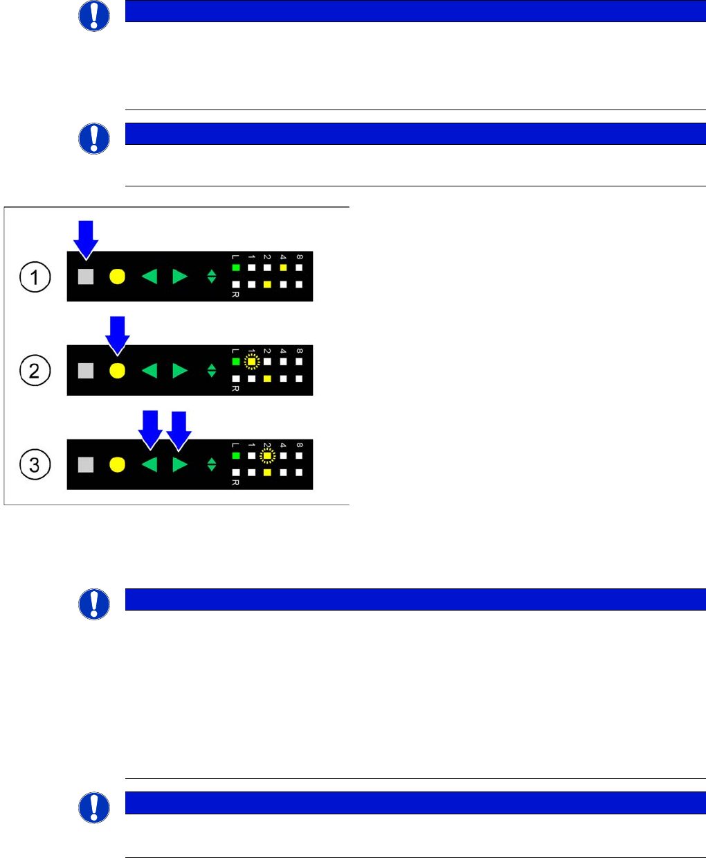
When adjusting the pickup position the pitch display is used to represent the different positions.
The positions are assigned as follows:
►Pickup position 1 - LED 1
►Pickup position 2 - LED 2
NOTICE
Before the adjustment it may be necessary to select the desired track using the Track change
button.
►(1) Initial status: To change the pickup position of the
selected track the Set button is pressed first. This
button must be pressed during the whole adjustment
process.
►(2) Activating the adjustment function: In addition to
the Set button the Foil button is briefly pressed and
released. As a consequence the pitch display of the
selected track indicates the currently set pickup posi-
tion by flashing fast.
►(3) Changing the pickup position: As long as the Set
button is pressed, the pickup position can be
changed by briefly pressing the Forwards or Back-
wards button. The pitch display of the selected track
indicates the changed pickup position by flashing
fast.
►Completing the adjustment: If the desired pickup posi-
tion is set the SET button must be released. The
feeder module saves the modification and the sprock-
et wheel is moved to the selected position.
NOTICE
When a pickup position has been set, the feeder module automatically sets a pitch in which
most components with the dimensions defined for this pickup position are packed. Thus, an ad-
ditional adjustment of the pitch is necessary in rare cases only.
When the adjustment is completed, the feeder module will automatically change the position of
the sprocket wheel, if the pickup position has changed.
Pickup position and pitch are assigned as follows:
►Pickup position 1 - 2 mm pitch
►Pickup position 2 - 4 mm pitch
NOTICE
8 mm pitch
The 8 mm pitch must be adjusted manually later on, if the machine does not specifies this pitch.
Operating Tape Feeder Modules
Adjusting the Pickup Positions Using the Operator Panel
User Manual X Feeder Modules SIPLACE Family 65
Pickup Position for 8 mm Pitch
When using tapes with an 8 mm component pitch, a component offset of 4 mm with respect to the pickup
position may occur after threading in the tape.
It is possible to correct this offset without changing the set 8 mm pitch and without re-threading the tape,
using the following function:
CAUTION
The adjustment is automatically cancelled, if the feeder module receives a request or conveyor
command from the machine or if the Set button is being pressed more than 30 seconds.
In these cases any modification made is cancelled and the previously set pickup position is re-
tained.
NOTICE
Before the adjustment it may be necessary to select the desired track using the Track change
button.
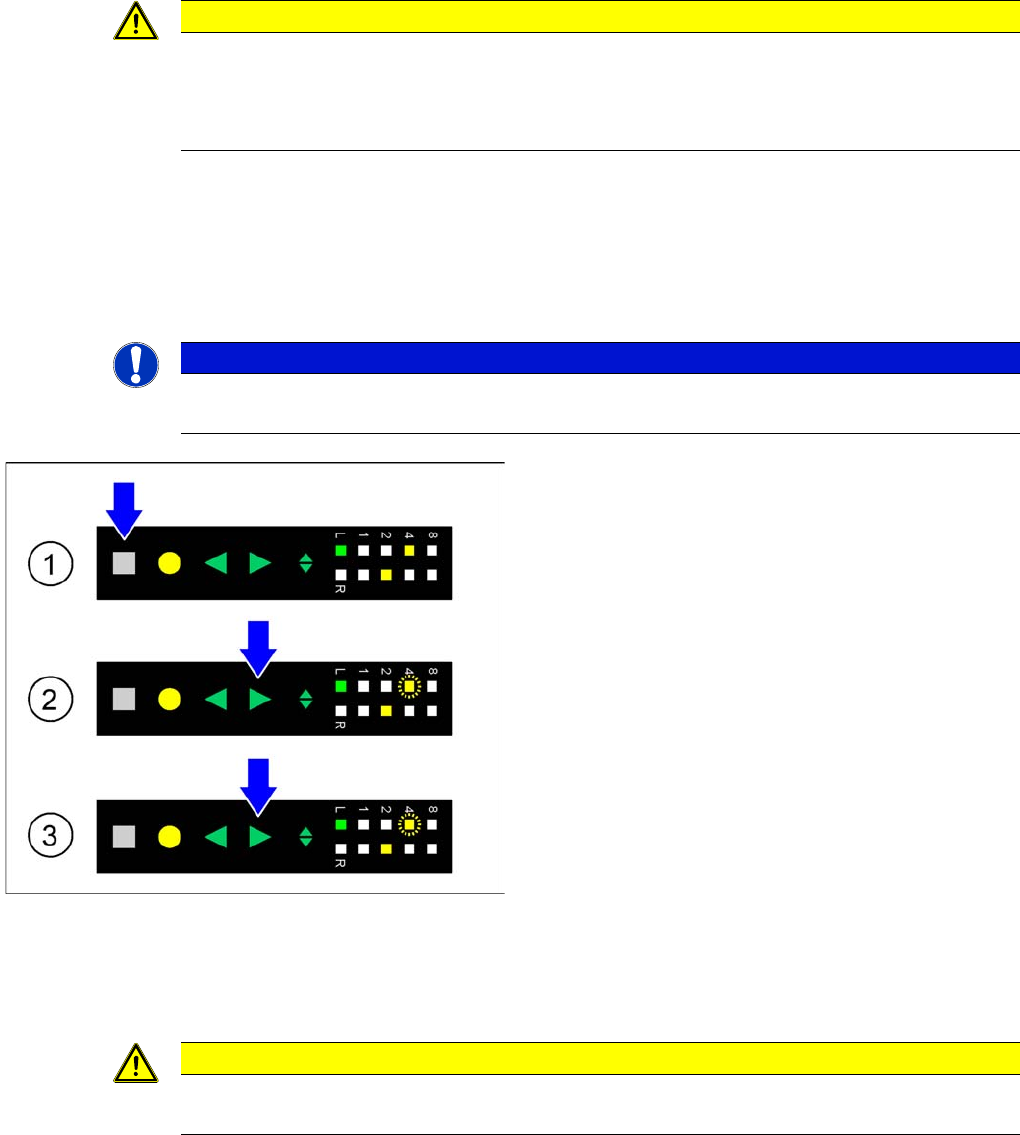
►(1) Initial status: To correct the pickup position of the
selected track by 4 mm, the press Set button first.
This button must be pressed during the whole adjust-
ment process.
►(2) Activating the adjustment function: In addition to
the Set button press the Forwards button; both but-
tons must be pressed simultaneously for at least 0.75
seconds. After this time LED 4 on the pitch display of
the selected track starts to flash slowly. At the same
time the tape is moved forwards in this track by 4 mm.
The Forwards button can now be released.
►(3) Changing the tape position: As long as the Set
button is pressed, you can move the tape forwards by
another 4 mm in the selected track, if necessary, by
briefly pressing the Forwards button. LED 4 on the
pitch display continues to flash slowly.
►Completing the adjustment: If the tape has reached its
desired position, the release Set button. The pitch
display shows the 8 mm pitch set for the selected
track.
CAUTION
The adjustment is automatically cancelled, if the feeder module receives a request or conveyor
command from the machine or if the Set button is being pressed more than 30 seconds.