00197295-01_UM_D4i_SR605_EN.pdf - 第116页
3 Technical data for the machine User manual SIPLACE D4i 3.8 Vision system From software ve rsion SR.605.03 SP2 10/2012 EN edition 116 3.8.1 C&P component camera, type 28, 18 x 18, digit al 3.8.1.1 Stru cture 3 Fig. …

User manual SIPLACE D4i 3 Technical data for the machine
From software version SR.605.03 SP2 10/2012 EN edition 3.8 Vision system
115
3.8 Vision system
A component camera is integrated into each Collect&Place head (see Fig. 3.5 - 1 page 96).
The component vision module is used to determine:
– the precise position of the components at the nozzle and
– the geometry of the package form.
The PCB vision module uses fiducials on the PCBs to determine:
– the position of the PCB,
– its rotation angle
– and the PCB skew.
The PCB cameras are fixed to the bottom of the gantries. They use fiducials on the feeder mod-
ules to determine the exact pick-up position of components, which is particularly important for
small components.
3 Technical data for the machine User manual SIPLACE D4i
3.8 Vision system From software version SR.605.03 SP2 10/2012 EN edition
116
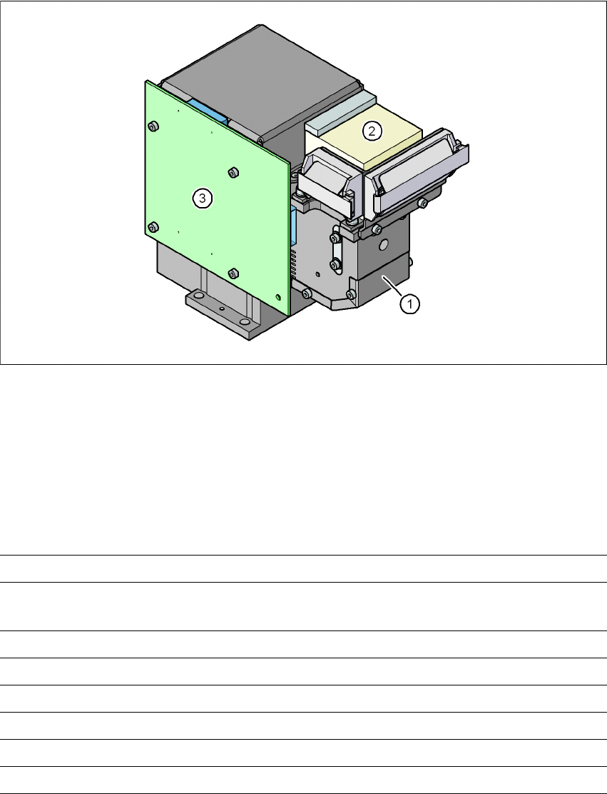
3.8.1 C&P component camera, type 28, 18 x 18, digital
3.8.1.1 Structure
3
Fig. 3.8 - 1 C&P component camera, type 28, 18 x 18, digital
3
(1) Component camera lens and illumination
(2) Camera amplifier
(3) Illumination control
3.8.1.2 Technical data
3
Component dimensions 0.5 x 0.5 mm² to 18.7 x 18.7 mm²
Range of components 0402 to PLCC44 incl. BGA, µBGA, flip-chip, TSOP, QFP,
SO to SO32, DRAM
Min. lead pitch 0.5 mm
Min. lead width 0.2 mm
Min. ball pitch 0.35 mm
Min. ball diameter 0.2 mm
Field of vision 24.5 x 24.5 mm²
Method of illumination Front-illumination (5 levels, programmable as required)
User manual SIPLACE D4i 3 Technical data for the machine
From software version SR.605.03 SP2 10/2012 EN edition 3.8 Vision system
117
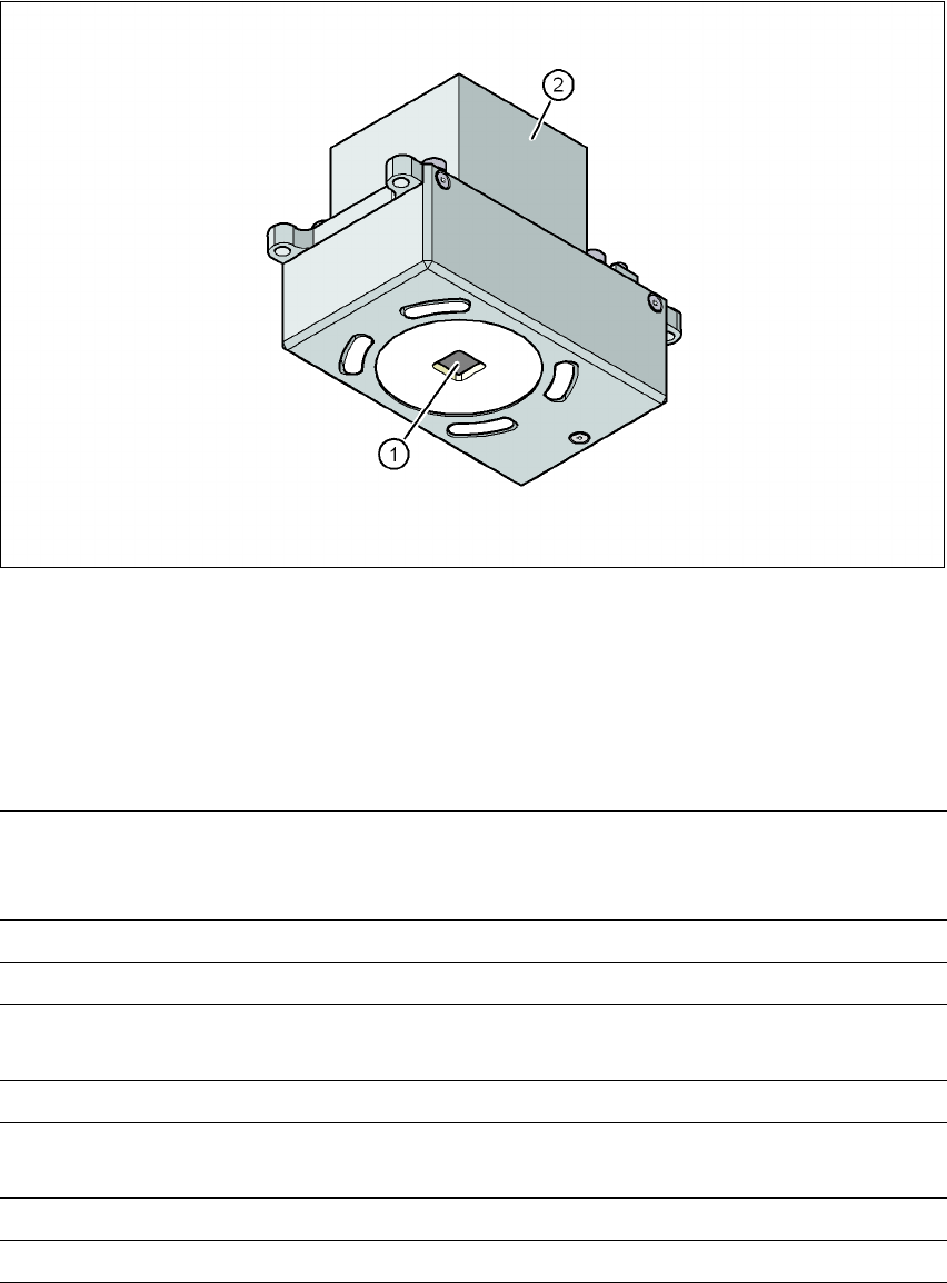
3.8.2 PCB camera, type 34, digital
3.8.2.1 Structure
3
Fig. 3.8 - 2 PCB camera, type 34, digital
(1) PCB camera lens and illumination
(2) Camera amplifier
3.8.2.2 Technical data
3
PCB fiducials Up to 3 (subpanels and multiple panels)
up to 6 for the Long board option (optional PCB fiducials are
output by the optimization.)
Local fiducials Up to 2 per PCB (may be of different type)
Library memory Up to 255 fiducial types per subpanel
Image analysis Edge detection method (Singular feature) based on grayscale
values
Method of illumination Front-illumination (3 levels, programmable as required)
Detection time per fiducial
/Bad fiducial
20 ms - 200 ms
Field of vision 5.78 x 5.78 mm²
Distance from the focus plane 28 mm