00197295-01_UM_D4i_SR605_EN.pdf - 第217页
User manual SIPLACE D4i 6 Station extensions From software version SR.605.03 SP2 10/2012 EN edition 6.1 Nozzle changer for the 12-nozzle Collect & Place head 217 6.1.3 Position of the nozzle changers for the C&P1…

6 Station extensions User manual SIPLACE D4i
6.1 Nozzle changer for the 12-nozzle Collect&Place head From software version SR.605.03 SP2 10/2012 EN edition
216
6.1.1 Description
This nozzle changer can hold up to 5 magazines, each with 12 nozzle holders. The magazines
are seated on a common carrier (see Fig. 6.1 - 1
, page 215). They are centered using two parallel
pins and fixed in place with clips.
A second nozzle changer can be optionally installed at each location (see item 6 in Fig. 6.1 - 2
,
page 217
).
6.1.2 Technical data
6
Nozzle changer for the 12-nozzle Collect&Place head
Dimensions (length x width x height) 472.5 x 63 x 77 mm³
Number of magazines 5, each with 12 nozzle holders
Nozzle types 9xx
Nozzle changeover time approx. 2s per nozzle
Compressed air connection 0.48 MPa (4.8 bar)
User manual SIPLACE D4i 6 Station extensions
From software version SR.605.03 SP2 10/2012 EN edition 6.1 Nozzle changer for the 12-nozzle Collect&Place head
217
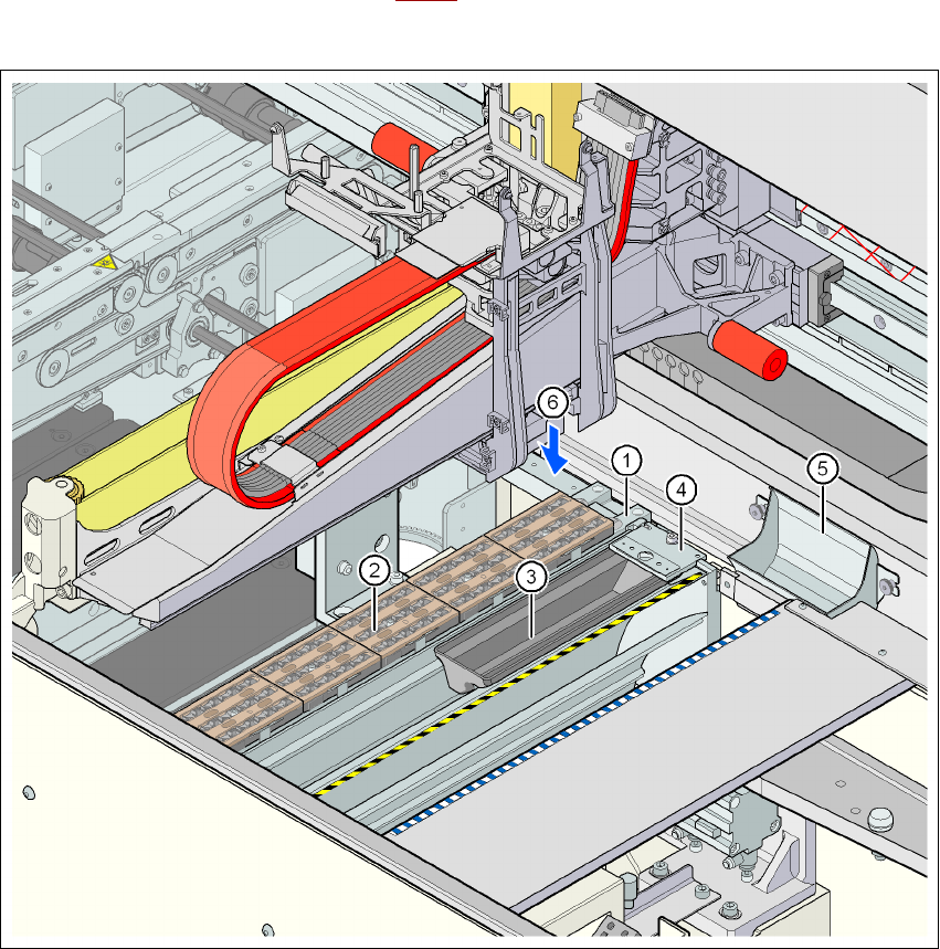
6.1.3 Position of the nozzle changers for the C&P12 head
At locations 1 to 4, two nozzle changers can be installed at each location for the 12-nozzle
Collect&Place head (item 1 and 6 in Fig. 6.1 - 2
). This gives a total capacity of 8 nozzle changers
with 40 magazines and 480 nozzle holders.
6
Fig. 6.1 - 2 Position of the nozzle changers for the 12-nozzle Collect&Place head
6
(1) Nozzle changer
(2) Nozzle magazine
(3) Reject bin for nozzles
(4) Take-off device for nozzles
(5) Reject bin for components
(6) Installation location for a second nozzle changer
6 Station extensions User manual SIPLACE D4i
6.1 Nozzle changer for the 12-nozzle Collect&Place head From software version SR.605.03 SP2 10/2012 EN edition
218
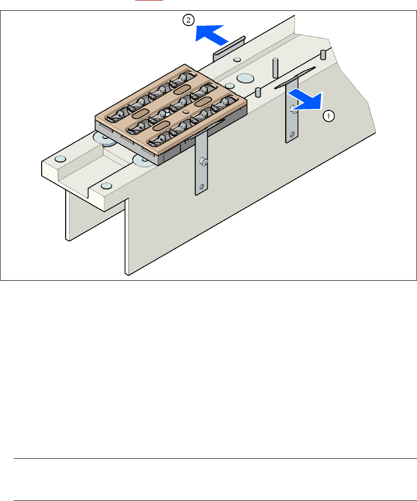
6.1.4 Assembly
Each nozzle changer (see Fig. 6.1 - 2) is fixed to the used tape channel.
6
Fig. 6.1 - 3 Assembly position
(1) Spring hook pointing toward the operator
(2) Retaining clamp pointing toward the PCB conveyor
→ Align the nozzle changer so that the moving spring hooks always point toward the operator,
while the retaining clamps always point toward the PCB conveyor.
6.1.5 Notes on operation
→ When you fill a magazine with a certain nozzle type for the first time, attach an adhesive label
to identify the type.
PLEASE NOTE 6
Fill the magazines off the machine and always replace complete magazines. 6
→ Open the locking plate and place the nozzles in the nozzle holders.
→ Close the locking plate so that the nozzles cannot drop out of the magazines.