00197295-01_UM_D4i_SR605_EN.pdf - 第139页
User manual SIPLACE D4i 3 Technical data for the machine From software version SR.605.03 SP2 10/2012 EN edition 3.10 Component trolley 139 3.10.7 Second level reel holder Item no. 001 19772-xx Second level reel holder D4…
3 Technical data for the machine User manual SIPLACE D4i
3.10 Component trolley From software version SR.605.03 SP2 10/2012 EN edition
138
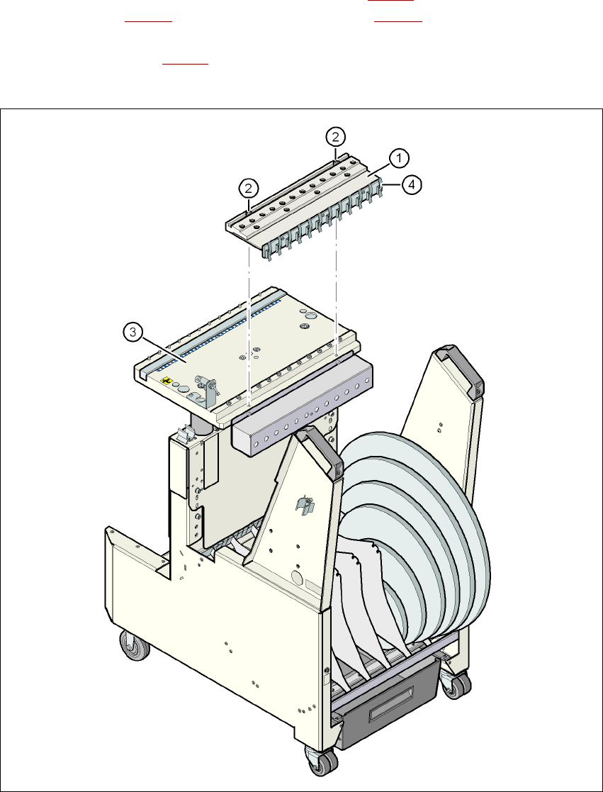
It is easy to fit. The compressed air distributor (item 1 in Fig. 3.10 - 5) is fastened to the component
table (item 3 in Fig. 3.10 - 5
) with two screws (item 2 in Fig. 3.10 - 5). The distributor is then con-
nected to the compressed air supply of the component trolley. The distributor has retaining clips
on the back (item 4 in Fig. 3.10 - 5
). They fix the bulk case feeder modules to the component table
and thus ensure a perfect compressed air supply.
3
Fig. 3.10 - 5 Compressed air supply for bulk case feeder modules
(1) Compressed air distributor
(2) DIN 912 screw, M8x20, 2x
(3) Component table
(4) Retaining clamps
User manual SIPLACE D4i 3 Technical data for the machine
From software version SR.605.03 SP2 10/2012 EN edition 3.10 Component trolley
139
3.10.7 Second level reel holder
Item no. 00119772-xx Second level reel holder D4i
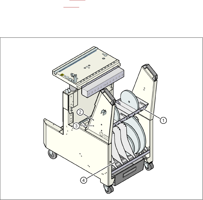
When using a maximum set-up of 3 x 8 mm feeder modules, the tape reels may be restrained in
the base container (item 4 in Fig. 3.10 - 6
) and impede the handling of the tape reels. The second
level reel holder (item 1 in Fig. 3.10 - 6
) allows to swap tape reels which are restrained in the base
container to the second level reel holder and thus to ease the handling. The elevated arrangement
of the second level reel holder improves the ergonomics when setting-up and refilling compo-
nents.
Fig. 3.10 - 6 Second level reel holder
(1) Second level reel holder
(2) Upper assembly position
(3) Lower assembly position
(4) Base container

3 Technical data for the machine User manual SIPLACE D4i
3.10 Component trolley From software version SR.605.03 SP2 10/2012 EN edition
140
The second level reel holder can be installed on the component trolley in two different height po-
sitions (item 4 in Fig. 3.10 - 6
, page 139). The maximum permitted reel size is seven inch.
When the component trolley height is set to 900 mm, the maximum reel diameter in the base con-
tainer can assume the following values depending on the assembly position:
3
The second level reel holder is half as wide as the component trolley. When ordering one reel hol-
der is delivered. It can be installed on the right or left component trolley side. If the full component
trolley width is to be used, you will need two second level reel holders.
Second level reel holder Max. reel diameter in the base container
Upper assembly position 13 inch
Lower assembly position 10 inch