00197295-01_UM_D4i_SR605_EN.pdf - 第15页
User manual SIPLACE D4i 1 Introduction From software version SR.605.03 SP2 10/2012 EN edition 1.1 Machine description 15 1 Fig. 1.1 - 1 The SIPLACE principle 1.1.3 New options and performance features The following o pti…
1 Introduction User manual SIPLACE D4i
1.1 Machine description From software version SR.605.03 SP2 10/2012 EN edition
14
1.1 Machine description
1.1.1 SIPLACE D4i placement machine
The high-speed placement machine SIPLACE D4i connects high placement rate with accuracy
and flexibility. The Collect&Place method is used as a placement procedure.
The SIPLACE D4i placement machine is equipped with four gantries which can be positioned
quickly and accurately in the X and Y directions.
There is a 12-nozzle Collect&Place head on each gantry. The gantries are combined in pairs to
form a common placement area.
Placement area 1: Gantries 1 and 4
Placement area 2: Gantries 2 and 3 1
The SIPLACE D4i placement machine is prepared to place 01005 components. For placement of
01005 components you simply need the optional 01005 package for the 12-nozzle Collect&Place
head. The component range ranges from 01005 components up to a size of 18.7 x 18.7 mm².
Digital vision modules perform the optical centering of the components. To do this there are digital
cameras available each with a different resolution.
A five-piece PCB conveyor, consisting of input belt, processing belt 1, intermediate belt, process-
ing belt 2 and output belt, carries the PCB into the processing position. As a further variant, it is
also possible to choose between the single conveyor or flexible dual conveyor with fixed side on
right or left. The PCBs are optically centered with the digital PCB camera.
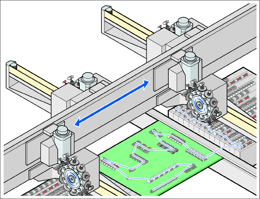
1.1.2 The SIPLACE principle
The moving head picks up the components from their stationary feeder, and places them on the
PCB, which is also stationary. This proven SIPLACE principle has many advantages:
– Short down times for refilling or splicing
– Even the smallest components (e.g. 01005) are picked up reliably
– The components cannot slip on the PCB
– Minimal traversing paths
High flexibility, cost-effectiveness and set-up reliability combine to ensure that the SIPLACE D4i
placement system provides high productivity. Minimum down times increase utilization and thus
help to increase productivity.
User manual SIPLACE D4i 1 Introduction
From software version SR.605.03 SP2 10/2012 EN edition 1.1 Machine description
15
1
Fig. 1.1 - 1 The SIPLACE principle
1.1.3 New options and performance features
The following options are available to extend the machines' functionality:
– 01005 package
The SIPLACE D4i placement machines are prepared to place 01005 components. For place-
ment simply retrofitting of the 12-nozzle Collect&Place head with the 01005 package is nec-
essary. For the upgrade to the 01005 package a new CO camera is no longer needed, if the
0201 package is installed. 1
– 0201 package
We can supply the 0201 package for processing 0201 components with the 12-nozzle
Collect&Place head. The 0201 package can be chosen as standard on the placement ma-
chines. 1
– Component trolley
The design of the component trolley has been revised. Fixed handles replace the folding han-
dles. This saves time when changing the component trolley. The new component trolley is
1 Introduction User manual SIPLACE D4i
1.1 Machine description From software version SR.605.03 SP2 10/2012 EN edition
16
downward compatible and therefore may also be used for the previous version of the ma-
chine. 1
– Second level reel holder
When using a maximum set-up of 3 x 8 mm feeder modules, the tape reels may be restrained
in the base container and impede the handling of the tape reels. The second level reel holder
allows to swap tape reels which are restrained in the base container to the second level reel
holder and thus to ease the handling. The elevated arrangement of the second level reel
holder improves the ergonomics when setting-up and refilling components. 1
– CO camera, type 30
The CO camera, type 30, replaces the CO cameras, type 29 and type 38. It allows to optically
center 0201 components as well as 01005 components. 1
– Machine protection
The protective cover was redesigned. The central ridge of the previous D series machines is
removed. When the protective covers are open, unrestricted access to the inside of the ma-
chine is possible. 1