00197295-01_UM_D4i_SR605_EN.pdf - 第138页
3 Technical data for the machine User manual SIPLACE D4i 3.10 Component trolley From software version SR.605.03 SP2 10/2012 EN edition 138 It is easy to fit. The co mpressed air di stributor (item 1 in Fig . 3.10 - 5 ) i…

User manual SIPLACE D4i 3 Technical data for the machine
From software version SR.605.03 SP2 10/2012 EN edition 3.10 Component trolley
137
3.10.4.1 Tape reel diameter in relation to the PCB conveyor height
3
3.10.5 External power supply for component trolley
Item no. 00119029-xx External power supply, feeder table D4i
Item no. 00119030-xx Extension cable, feeder table
To keep the time required for a setup change as short as possible, component trolleys can be set
up in advance at a special external location. The feeder module functions and setting can be
checked there to prepare for use. We provide an external power supply for this purpose. The com-
ponent trolley with the required electrical power and compressed air is supplied via a connecting
cable.
3.10.5.1 Technical data
The kit contains a main power cable to European standards, a main power cable to US standards
and a connecting cable between the power supply and the component trolley.
3.10.6 Compressed air supply for bulk case feeder modules
Item no. 00119028-xx Bulk case compressed air distributor
Bulk case feeder modules require compressed air in order to work. A compressed air supply for
bulk case feeder modules is therefore available as an option.
Option –
With support for 3rd tape
reel
PCB conveyor height
of the component trolley
Tape reel diameter Tape reel diameter
830 mm 17" 15"
900 mm 19" 17"
930 mm 19" 17"
950 mm 19" 19"
Main power voltage 230 VAC ± 5 %
120 VAC ± 5 %
Compressed air connection Max. 1.0 MPa (10 bar)
Output pressure Can be adjusted with pressure regulator
3 Technical data for the machine User manual SIPLACE D4i
3.10 Component trolley From software version SR.605.03 SP2 10/2012 EN edition
138
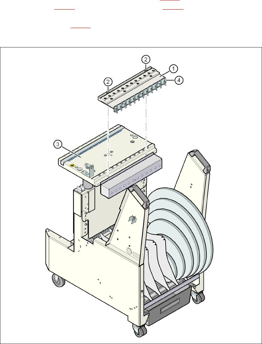
It is easy to fit. The compressed air distributor (item 1 in Fig. 3.10 - 5) is fastened to the component
table (item 3 in Fig. 3.10 - 5
) with two screws (item 2 in Fig. 3.10 - 5). The distributor is then con-
nected to the compressed air supply of the component trolley. The distributor has retaining clips
on the back (item 4 in Fig. 3.10 - 5
). They fix the bulk case feeder modules to the component table
and thus ensure a perfect compressed air supply.
3
Fig. 3.10 - 5 Compressed air supply for bulk case feeder modules
(1) Compressed air distributor
(2) DIN 912 screw, M8x20, 2x
(3) Component table
(4) Retaining clamps
User manual SIPLACE D4i 3 Technical data for the machine
From software version SR.605.03 SP2 10/2012 EN edition 3.10 Component trolley
139
3.10.7 Second level reel holder
Item no. 00119772-xx Second level reel holder D4i
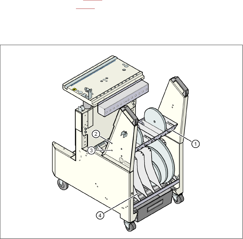
When using a maximum set-up of 3 x 8 mm feeder modules, the tape reels may be restrained in
the base container (item 4 in Fig. 3.10 - 6
) and impede the handling of the tape reels. The second
level reel holder (item 1 in Fig. 3.10 - 6
) allows to swap tape reels which are restrained in the base
container to the second level reel holder and thus to ease the handling. The elevated arrangement
of the second level reel holder improves the ergonomics when setting-up and refilling compo-
nents.
Fig. 3.10 - 6 Second level reel holder
(1) Second level reel holder
(2) Upper assembly position
(3) Lower assembly position
(4) Base container