00197295-01_UM_D4i_SR605_EN.pdf - 第223页
User manual SIPLACE D4i 6 Station extensions From software version SR.605.03 SP2 10/2012 EN edition 6.2 PCB bar code scanner 223 6 Fig. 6.2 - 2 1D and 2D barcode scanners The PCB barcode scanners ar e fixed to the top an…

6 Station extensions User manual SIPLACE D4i
6.2 PCB barcode scanner From software version SR.605.03 SP2 10/2012 EN edition
222
6.2 PCB barcode scanner
6.2.1 Description
Item no. 00119682-xx 1D PCB barcode scanner
Item no. 00119679-xx 2D PCB barcode scanner
Item no. 00119430-xx PCB barcode scanner assembly kit
The PCB barcode scanner is used to automatically record and decode barcodes on PCBs. The
PCB barcode scanner sends the read data via its serial interface to the transport controller and
then for further processing to the machine controller via the CAN bus.
6
Fig. 6.2 - 1 PCB barcode block diagram
The PCB barcode scanners are installed on the input side of the placement machine on the PCB
conveyor. Up to four devices can be retrofitted to each machine. The barcode scanners are fitted
so that the barcode labels on the topside and underside of the PCBs can be scanned on both
tracks of the dual conveyor.
There are two variants of the barcode scanner:
– 1D barcode scanner
This barcode scanner processes barcodes. 6
– 2D barcode scanner
This barcode scanner processes matrix code. Matrix code is primarily used when there
is not enough space for barcode labels. The 2D barcode scanner also reads conven-
tional barcodes. 6
Device number
1
BC
scanner
top
Distribution
board
Transport
controller,
right
BC
scanner
bottom
2
3
BC
scanner
top
Distribution
board
Transport
controller,
left
BC
scanner
bottom
4
Machine
controller
Control
computer
SIPLACE Pro
computer
LANCAN busV-24V-24
User manual SIPLACE D4i 6 Station extensions
From software version SR.605.03 SP2 10/2012 EN edition 6.2 PCB barcode scanner
223
6
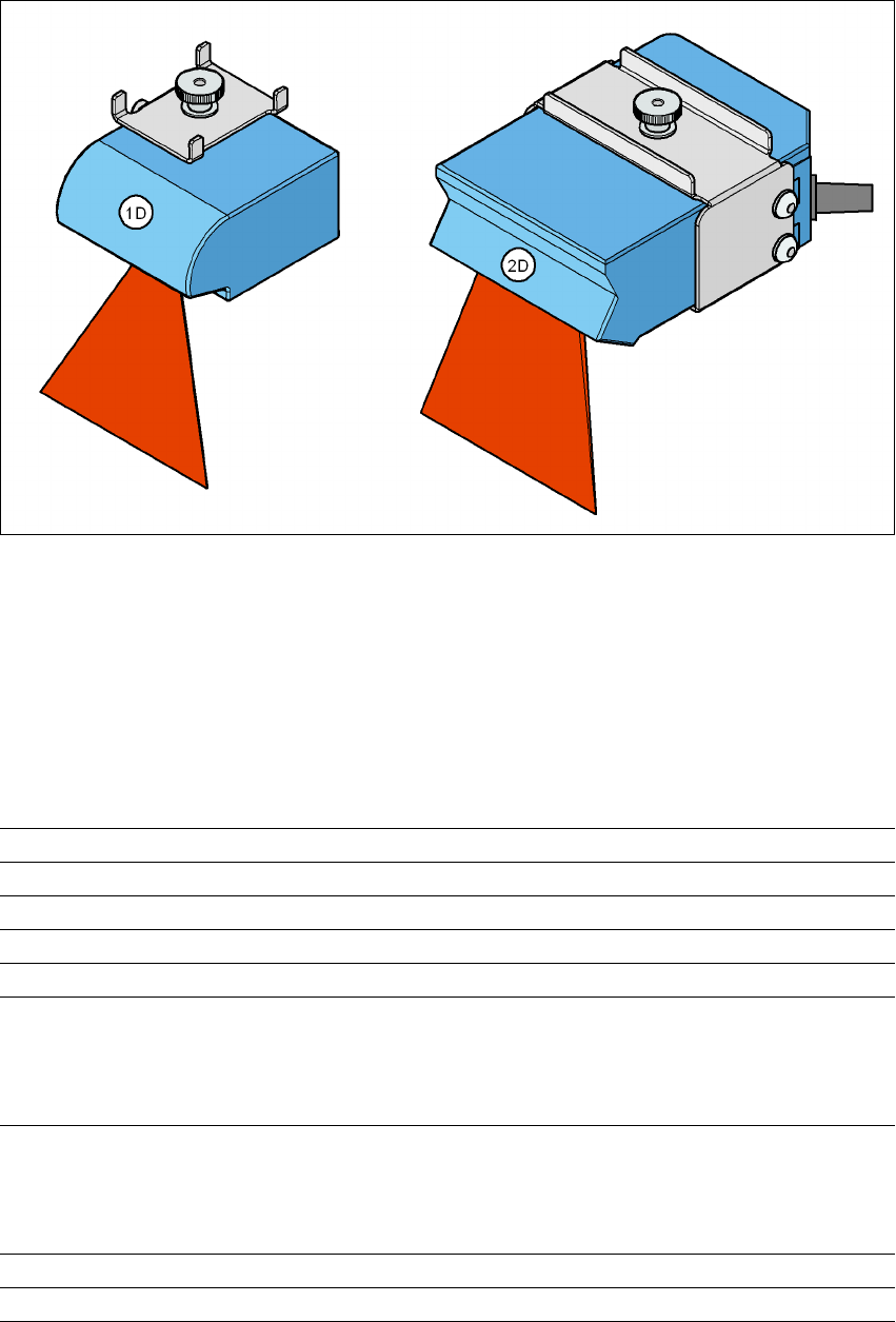
Fig. 6.2 - 2 1D and 2D barcode scanners
The PCB barcode scanners are fixed to the top and bottom profiled rail using retainers. These can
be positioned as required on the profiled rails, and aligned with respect to the barcode labels. De-
pending on the position of the barcode strips, the barcode scanner can be attached in a few simple
steps so that the strips can be read parallel to or across the PCB transport direction.
6.2.2 Technical data – 1D barcode scanner
6
Laser diode Red light
Wave length 670 nm
Laser class Class 2, as per DIN EN 60825-1:2001
Scanning frequency 400 ... 1200 Hz
Resolution 0.15 mm ... 0.5 mm
Code types Code 39, Code 128, Code 93,
Codabar, EAN, EAN 128, UPC,
2/5 Interleaved, Pharma Code
(others available on request)
Barcode length
Single conveyor
Dual conveyor, asynchronous
Dual conveyor, synchronous
Max. 40 characters
Max. 40 characters
Max. 40 characters
Optical display 4 x LED function display
Audible indicator Buzzer

6 Station extensions User manual SIPLACE D4i
6.2 PCB barcode scanner From software version SR.605.03 SP2 10/2012 EN edition
224
6
6.2.3 Technical data – 2D barcode scanner
6
6
Data interface RS232, RS 422/485
Electrical connection 15-pin D-Sub HD connector
Operating voltage 10 VDC ... 30 VDC
Laser diode Red light
Wave length 650 nm
Laser class Class 2, as per DIN EN 60825-1:2001
Scanning frequency 100 ... 15 kHz
Resolution 0.17 mm ... 0.5 mm
2D code types Data Matrix ECC 200
2D barcode length
Single conveyor
Dual conveyor, asynchronous
Dual conveyor, synchronous
Max. 40 characters
Max. 40 characters
Max. 40 characters
1D code types Code 39, Code 128,
Codabar, EAN, EAN 128, UPC,
2/5 Interleaved, Pharma Code
(others available upon request)
1D barcode length
Single conveyor
Dual conveyor, asynchronous
Dual conveyor, synchronous
Max. 40 characters
Max. 40 characters
Max. 40 characters
Optical display 4 x LED function display
Audible indicator Buzzer
Data interface RS232, RS 422/485, Ethernet
Electrical connection 15-pin D-Sub HD connector
RJ45 connector 10baseT
Operating voltage 10 VDC ... 30 VDC