00197295-01_UM_D4i_SR605_EN.pdf - 第176页
4 Setting up and commissioning User manual SIPLACE D4i 4.4 Adapting the component trolley to the PCB conveyor height From software version SR.605.03 SP2 10/2012 EN edition 176 4 Fig. 4.4 - 1 Position of the eye-bolt on t…
User manual SIPLACE D4i 4 Setting up and commissioning
From software version SR.605.03 SP2 10/2012 EN edition 4.4 Adapting the component trolley to the PCB conveyor height
175
4.4.3 Changing the component trolley height
WARNING 4
Remove all the feeder modules from the component trolley table bed.
→ Screw the eye-bolt into the M12 hole (item 1 in Fig. 4.4 - 1
, page 176) in the component trolley
table bed.
→ Attach the hooks of the lifting device to the eye-bolt (item 2 in Fig. 4.4 - 1
, page 176).
→ Tighten the cable of the lifting device.
→ Loosen the 8 hexagon socket head screws, M6x12 (item 4 in Fig. 4.4 - 1
, page 176).
→ Raise or lower the component trolley table to the desired height,
→ Check the preset height with reference to the position of the check hole. The check hole for
the selected height must not be covered by the column.
→ If necessary, correct the height so that the holes for the fixing screws in the bridge are aligned
with the threaded holes in the vertical threaded rails (see figures on page 177
, 179, 181 and
183
.
→ Fix the bridge (item 5) to the vertical threaded rails using the 8 hexagon socket head screws
and washers. The positions of the hexagon socket head screws are shown in figures 4.4 - 2
to 4.4 - 9
.
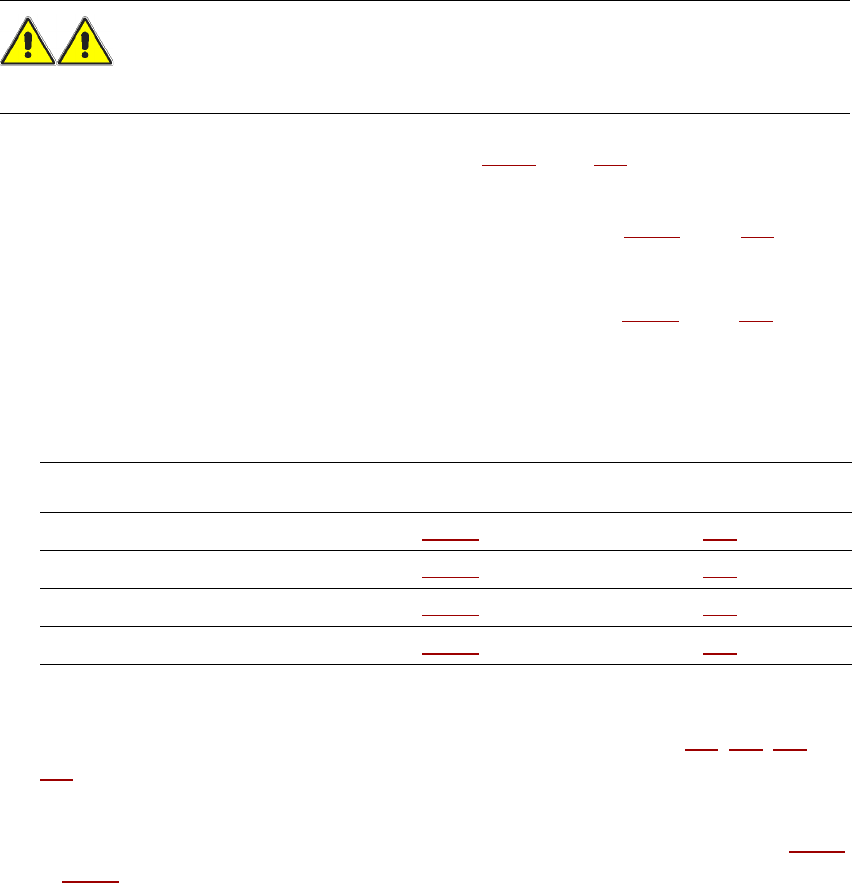
PCB conveyor height Figure Page
830 mm 4.4 - 2
177
900 mm 4.4 - 4 179
930 mm 4.4 - 6 181
950 mm 4.4 - 8 183
4 Setting up and commissioning User manual SIPLACE D4i
4.4 Adapting the component trolley to the PCB conveyor height From software version SR.605.03 SP2 10/2012 EN edition
176
4
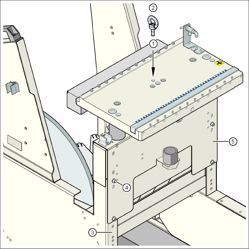
Fig. 4.4 - 1 Position of the eye-bolt on the component trolley
(1) M12 hole for eye-bolt
(2) Eye-bolt, DIN 580 M12-St
(3) Vertical threaded rail
(4) Hexagon socket head screw, M6x12 with washer, 8 x
(5) Jumper
User manual SIPLACE D4i 4 Setting up and commissioning
From software version SR.605.03 SP2 10/2012 EN edition 4.4 Adapting the component trolley to the PCB conveyor height
177
4.4.4 830 mm PCB conveyor height
4
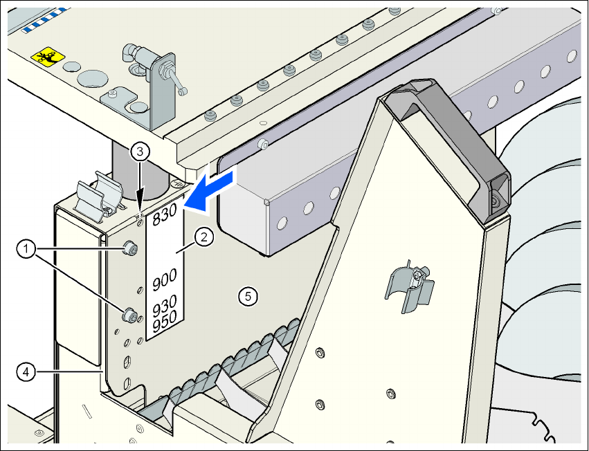
Fig. 4.4 - 2 Component trolley: PCB conveyor height 830 mm - back view, position of the hexagon socket head
screw and check hole
(1) Hexagon socket head screw M6x12 and washer (4x on the rear panel)
(2) Sticker with the heights 830, 900, 930 and 950 mm for the check holes
(3) 4 check holes for checking the preset height. The selected height is preset correctly if the
check hole is not covered by the vertical threaded rail (item 4) (see arrow in the figure).
(4) Vertical threaded rail
(5) Jumper