00197295-01_UM_D4i_SR605_EN.pdf - 第165页
User manual SIPLACE D4i 4 Setting up and commissioning From software version SR.605.03 SP2 10/2012 EN edition 4.3 Setting up the machine 165 4.3.7 Machine foot clear ances and the stationary PCB conveyor edges 4.3.7.1 Ma…

4 Setting up and commissioning User manual SIPLACE D4i
4.3 Setting up the machine From software version SR.605.03 SP2 10/2012 EN edition
164
→ Use the M24 nuts to set the height of the middle machine feet (item 31 in Fig. 4.3 - 2, page
162
) to the following values:
4.3.5 Fitting the indicator lamps
→ Remove both upper cover plates.
→ Connect the indicator lamps cables to the cables on the basic machine.
→ Insert the indicator lamp into the hole until the tube of the indicator lamp projects sufficiently
into the terminal beneath.
→ Tighten the hexagon socket head screw on the terminal.
→ Fasten both upper cover plates.
4.3.6 Fixing the monitors
→ Fix the monitors and connect the cables.
→ Check the cable connections
PCB conveyor height Distance from underside of middle machine foot to
bottom edge of machine frame
900 mm 180 mm
930 mm 210 mm
950 mm 232 mm
User manual SIPLACE D4i 4 Setting up and commissioning
From software version SR.605.03 SP2 10/2012 EN edition 4.3 Setting up the machine
165
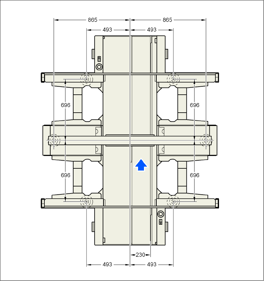
4.3.7 Machine foot clearances and the stationary PCB conveyor edges
4.3.7.1 Machine foot clearances and the stationary right conveyor edge for the
PCB single conveyor
4
Fig. 4.3 - 3 Machine foot clearances and the stationary right conveyor edge for the PCB single conveyor
4 Setting up and commissioning User manual SIPLACE D4i
4.3 Setting up the machine From software version SR.605.03 SP2 10/2012 EN edition
166
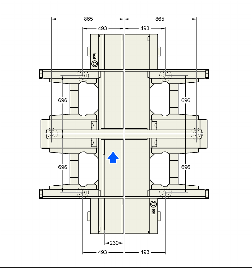
4.3.7.2 Machine foot clearances and the stationary left conveyor edge for the
PCB single conveyor
4
Fig. 4.3 - 4 Machine foot clearances and the stationary left conveyor edge for the PCB single conveyor