00197295-01_UM_D4i_SR605_EN.pdf - 第211页
User manual SIPLACE D4i 5 Tasks for the operating personnel From software version SR.605.03 SP2 10/2012 EN edition 5.10 Docking the component trolley in or out 211 Fig. 5.10 - 1 Docking the component trolley in or out 5 …
5 Tasks for the operating personnel User manual SIPLACE D4i
5.10 Docking the component trolley in or out From software version SR.605.03 SP2 10/2012 EN edition
210
5.10 Docking the component trolley in or out
WARNING 5
→ Please follow the safety instructions for docking the component trolley in and out described
in Section 2.5.2, page 52.
5.10.1 Docking out the component trolley
→ Click on the STOP PROCESSING PCB icon in the MAIN VIEW menu.
The PCB in progress will be completed. The icons of the single functions menu will then be
activated. 5
→ Click on the desired icon SINGLE FUNCTIONS GANTRY.
→ Select GANTRY FUNCTIONS.
→ From this menu, click on the GO TO SET-UP POSITION button.
All the placement heads will move across the PCB conveyor to prevent them being damaged
when the component trolley is changed. 5
→ Open the protective cover of the selected gantry.
→ Open the cover over the button for the lifting mechanism for the component table bed (see
Fig. 5.10 - 1
, item 1, page 211).
WARNING DANGER OF CRUSHING 5
When raising the component table bed, never reach into the gap between the feeders and
the used tape channel. 5
→ Turn the switch on the component table (item 4 in Fig. 5.10 - 1
, page 211) up.
→ Press the button (item 1 in Fig. 5.10 - 1
, page 211) until the component table bed (item 3 in
Fig. 5.10 - 1
, page 211) has reached the upper final position.
→ Unplug the supply cable of the component trolley from the socket on the station (item 2 in Fig.
5.10 - 1
, page 211).
User manual SIPLACE D4i 5 Tasks for the operating personnel
From software version SR.605.03 SP2 10/2012 EN edition 5.10 Docking the component trolley in or out
211
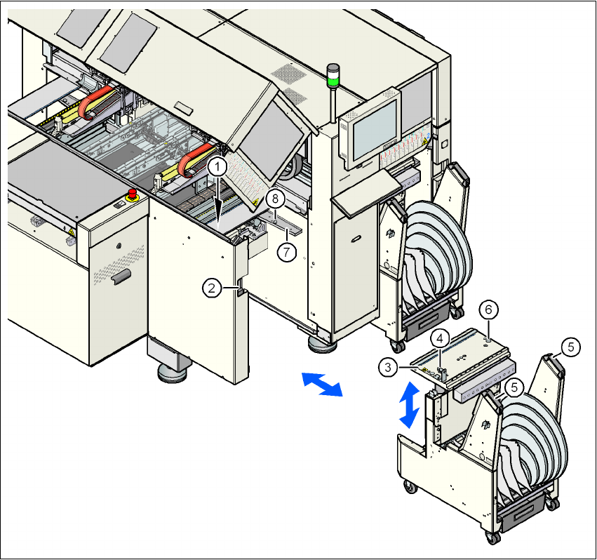
Fig. 5.10 - 1 Docking the component trolley in or out
5
(1) Button for raising the component table bed (beneath the cover flap)
(2) Plug for connecting the component trolley cable
(3) Component table bed, can be raised or lowered
(4) Switch for lowering the component table bed
(5) CO trolley handle
(6) Centering hole for the centering pins
(7) Supporting surface for the component table bed (right and left)
(8) Centering pin for the component table bed
5 Tasks for the operating personnel User manual SIPLACE D4i
5.10 Docking the component trolley in or out From software version SR.605.03 SP2 10/2012 EN edition
212
→ With both hands on the handles, pull the component trolley out of the machine.
→ Turn the switch on the component table (item 4 in Fig. 5.10 - 1
) down. The component table
is lowered.
WARNING 5
→ Please follow the safety instructions for moving the component trolley described in Section
2.5.4, page 53.
5.10.2 Docking in the component trolley
PLEASE NOTE 5
Shorten the component tapes on the front end of the S feeder modules to approximately 1 cm
before you dock in the component trolley.
CAUTION 5
Check that the placement head is outside the range of the component trolley.
→ Make sure that the left and right contact surfaces (item 7 in Fig. 5.10 - 1
, page 211) for the
component table bed is clean.
→ Check that the contact surfaces on the underside of the component table bed are clean.
→ CAREFULLY push the component trolley into the machine.
→ Plug the connecting cable of the component trolley into the socket (item 2 in Fig. 5.10 - 1
,
page 211
) on the machine.
→ Open the cover over the push-button used to raise and lower the component table bed (item
1 in Fig. 5.10 - 1
, page 211).
→ Turn the switch on the component table (item 4 in Fig. 5.10 - 1
, page 211) up.
→ Press the button (item 1 in Fig. 5.10 - 1
, page 211) until the component table bed has reached
the upper final position.
→ Carefully push the component trolley into machine as far as the stop.
→ Check that the centering holes in the component table bed lie precisely over the centering
pins of the machine (item 8 in Fig. 5.10 - 1
, page 211).