00197295-01_UM_D4i_SR605_EN.pdf - 第184页
4 Setting up and commissioning User manual SIPLACE D4i 4.4 Adapting the component trolley to the PCB conveyor height From software version SR.605.03 SP2 10/2012 EN edition 184 4 Fig. 4.4 - 9 Component trolley: PCB convey…
User manual SIPLACE D4i 4 Setting up and commissioning
From software version SR.605.03 SP2 10/2012 EN edition 4.4 Adapting the component trolley to the PCB conveyor height
183
4.4.7 950 mm PCB conveyor height
4
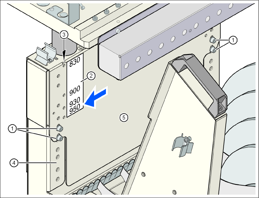
Fig. 4.4 - 8 Component trolley: PCB conveyor height 950 mm - back view, position of the hexagon socket head
screw and check hole
(1) Hexagon socket head screw M6x12 and washer (4x on the rear panel)
(2) Sticker with the heights 830, 900, 930 and 950 mm for the check holes
(3) 4 check holes for checking the preset height. The selected height is preset correctly if the
check hole is not covered by the vertical threaded rail (item 4) (see arrow in the figure).
(4) Vertical threaded rail
(5) Jumper
4 Setting up and commissioning User manual SIPLACE D4i
4.4 Adapting the component trolley to the PCB conveyor height From software version SR.605.03 SP2 10/2012 EN edition
184
4
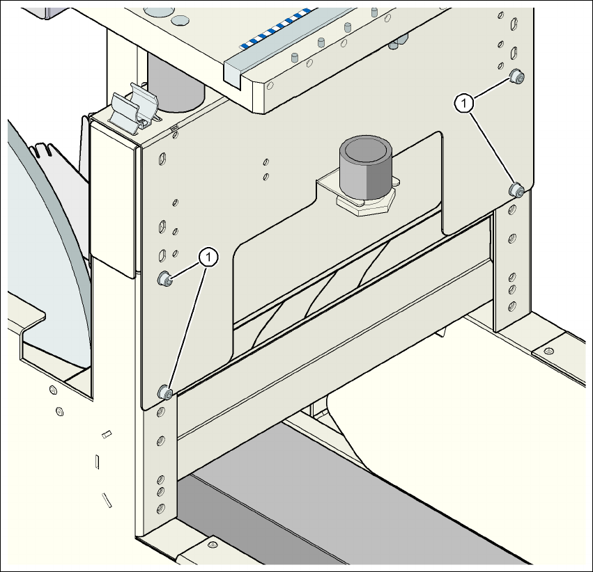
Fig. 4.4 - 9 Component trolley: PCB conveyor height 950 mm - front view, position of the hexagon socket head
screws
(1) Hexagon socket head screw M6x12 and washer (4x on the rear panel)

User manual SIPLACE D4i 4 Setting up and commissioning
From software version SR.605.03 SP2 10/2012 EN edition 4.5 Commissioning the machine
185
4.5 Commissioning the machine
4.5.1 Commissioning the machine at the customer's premises
→ Check all modules for correct seating.
→ Wipe off the linear guide rails with a lint-free cloth before removing the shipping braces for the
X/Y axis. Do not use any solvent to do this (see Section 4.3.11
, page 173.
→ Switch on the machine and perform a reference run.
→ Copy the placement program onto the computer and test it.
→ Check the machine zero point after a period of warming up of 3 - 4 h.
→ Get the customer's operating personnel to equip the feeder modules according to the cus-
tomer's placement program.
→ Instruct them in handling the feeder modules using the JobGuide.
→ Check all customer-specific installed options (in particular software) for good functioning and
order any necessary spare parts using the order form or by fax.
4.5.2 Instructing the customer's personnel
→ Explain all customer-specific installed options, in particular software / software compatibility.
→ Explain programming of the program editors on the line computer / SIPLACE Pro.
→ Instruct the operators and line engineers in using the station software.
→ Explain about password protection.
→ Instruct the customer personnel in preventive maintenance and care on the basis of the Job-
Guide.
4.5.3 A test run or starting production
→ Test the line using the test PCB or a PCB provided by the customer.
→ Record the customer product and performance data, prepare the data and document the data
in the installation report.
→ Secure the data and give the customer security copies.