00197295-01_UM_D4i_SR605_EN.pdf - 第170页
4 Setting up and commissioning User manual SIPLACE D4i 4.3 Setting up the machine From software version SR.605.03 SP2 10/2012 EN edition 170 4 Fig. 4.3 - 7 Contact surfaces - Forks across the direction of PCB transpor t …

User manual SIPLACE D4i 4 Setting up and commissioning
From software version SR.605.03 SP2 10/2012 EN edition 4.3 Setting up the machine
169
4.3.8 Integrating the machine into the line
→ Note the warning instructions described in Section 4.3.2, page 159.
→ The tools and equipment are listed in Section 4.3.3
, page 160.
4.3.8.1 Positioning the fork lift
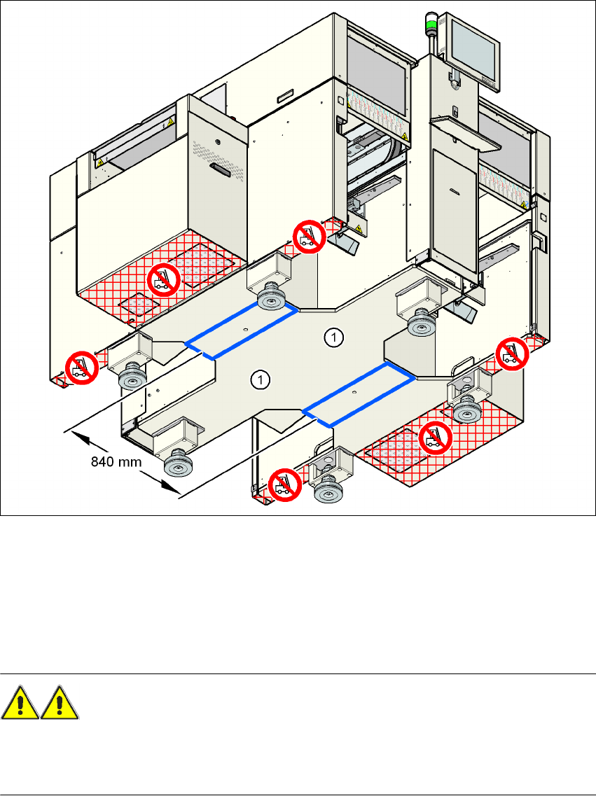
→ Position the fork-lift across the PCB travel direction and open the forks far enough so that the
machine's contact surface lies evenly on the forks (see Fig. 4.3 - 7
).
WARNING 4
Please note the following points before you raise the machine in order to avoid irreversible dam-
age to the machine:
– The distance between the forks must be between 800 and 900 mm. The attachment surfaces
for the fork-lift are shown in Fig. 4.3 - 7
, page 170. The average distance between the contact
surfaces is 840 mm. NEVER increase the distance between the forks so that the machine is
lifted on the side parts of the machine frame, since this would deform the machine frame.
→ Make sure that the forks are evenly loaded when you lift the machine. A firm support between
the forks and machine will prevent the machine tilting when it is raised. This will also prevent
a one-sided load on the machine feet, which would deform the fixing of the machine feet. We
recommend that a second person watch the machine as it is raised, and make sure that the
machine does not tip to one side when lifted with the fork-lift.
4 Setting up and commissioning User manual SIPLACE D4i
4.3 Setting up the machine From software version SR.605.03 SP2 10/2012 EN edition
170
4
Fig. 4.3 - 7 Contact surfaces - Forks across the direction of PCB transport
(1) Contact surfaces for the forks of the fork-lift
4
4
4
4.3.8.2 Points that MUST be noted when transporting the machine
WARNING 4
When you are transporting the machine, make sure that all the feet are clear of the floor. If they
are not clear, the feet will drag along the floor or bump into obstacles. This could damage the
machine foot fixing in the machine frame.
User manual SIPLACE D4i 4 Setting up and commissioning
From software version SR.605.03 SP2 10/2012 EN edition 4.3 Setting up the machine
171
4.3.8.3 Aligning the machine with respect to the line
→ Position the machine on the free location on the line using the fork-lift.
WARNING 4
Lower the machine slowly. A second person should look underneath to ensure that all the
machine foot touch the floor at the same time. If the machine feet on one side hit the ground
hard, the fixings may be damaged.
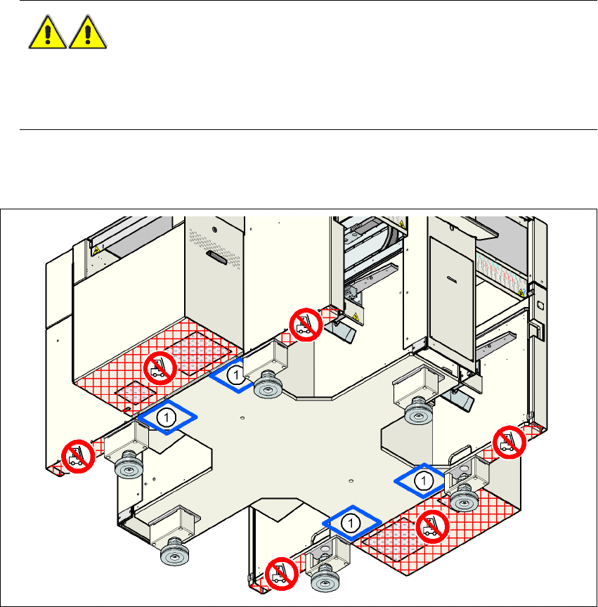
4.3.8.4 Aligning the machine with the air cushion transport system
4
Fig. 4.3 - 8 Contact positions for the air cushion transport system
(1) Contact surfaces for the air cushion transport system
→ Place the four air cushions of the air cushion transport system beneath the machine frame.
→ Raise the machine and align it with respect to the line.
→ Check the distance from the PCB conveyor system of the adjacent machine. It should be be-
tween 1 mm and 3 mm.
→ Lower the machine.