00197295-01_UM_D4i_SR605_EN.pdf - 第141页
User manual SIPLACE D4i 4 Setting up and commissioning From software version SR.605.03 SP2 10/2012 EN edition 4.1 Transport and delivery configuration 141 4 Setting up and commissioning 4.1 T ransport and delivery config…

3 Technical data for the machine User manual SIPLACE D4i
3.10 Component trolley From software version SR.605.03 SP2 10/2012 EN edition
140
The second level reel holder can be installed on the component trolley in two different height po-
sitions (item 4 in Fig. 3.10 - 6
, page 139). The maximum permitted reel size is seven inch.
When the component trolley height is set to 900 mm, the maximum reel diameter in the base con-
tainer can assume the following values depending on the assembly position:
3
The second level reel holder is half as wide as the component trolley. When ordering one reel hol-
der is delivered. It can be installed on the right or left component trolley side. If the full component
trolley width is to be used, you will need two second level reel holders.
Second level reel holder Max. reel diameter in the base container
Upper assembly position 13 inch
Lower assembly position 10 inch
User manual SIPLACE D4i 4 Setting up and commissioning
From software version SR.605.03 SP2 10/2012 EN edition 4.1 Transport and delivery configuration
141
4 Setting up and commissioning
4.1 Transport and delivery configuration
4.1.1 Shipping packaging
Within Europe, the machine and the CO trolleys are supplied on two pallets and wrapped in plastic
film. They will be dispatched overseas in two robust wooden crates.
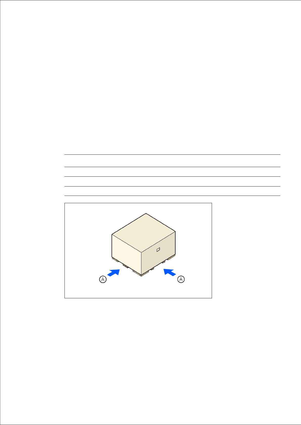
4.1.1.1 Dimensions of the shipping packaging
4
4
4
Fig. 4.1 - 1 Transport crate - dimension in millimeters
(A) Fork-lift attachment points
Crate for the machine Crate for the component trolleys
Length 2600 mm 1705 mm
Width 2400 mm 1200 mm
Height 1840 mm 1300 mm
4 Setting up and commissioning User manual SIPLACE D4i
4.1 Transport and delivery configuration From software version SR.605.03 SP2 10/2012 EN edition
142
4.1.1.2 Weight of the machine prepared for dispatch
The following table contains the weights of the machines prepared for dispatch, including packag-
ing.
4
4.1.2 Configuration when delivered
The machine is configured as follows when delivered:
– The track on the single conveyor is set to a width of 210 mm. On the dual conveyor, the width
of conveyor track 1 is 100 mm and conveyor track 2 is 210 mm. These preset PCB conveyor
widths make it easier to remove the extension kits and conveyors on the input or output side
of the machine when this is necessary for reasons of space in order to transport the machine.
– Both keyboards (item 1 in Fig. 4.1 - 2
) are unplugged.
– The supporting plates for the keyboards (item 2 in Fig. 4.1 - 2
) are detached.
– Both monitors (item 3 in Fig. 4.1 - 2
) are dismantled.
– Both indicator lamps (item 4 in Fig. 4.1 - 2
) are dismantled.
– All the gantry axes are fixed with shipping braces.
Weight Dispatch within Europe Dispatch overseas
Machine 3187 kg 3455 kg
CO trolley 458 kg 552 kg