OM-1833-001w_SL.pdf - 第103页
7. Reference T aping Specications 7.1 Allowable Limit of Edge W aving of T ape Allowable limit of edge waving of tape should be or less than 1 mm per 100 mm through a length of 250 mm as illustrated. 1 or less 1 or less…
(e) The cover tape should run smoothly along the sprocket holes.
The edges of the cover tape should be aligned with the carrier tape (taping).
The thickness of the cover tape should be 0.07 mm or less (including waste
paper).
(f) Use a taping on condition that the component itself or its electrical contact
is not protruded from the upper surface of tape.
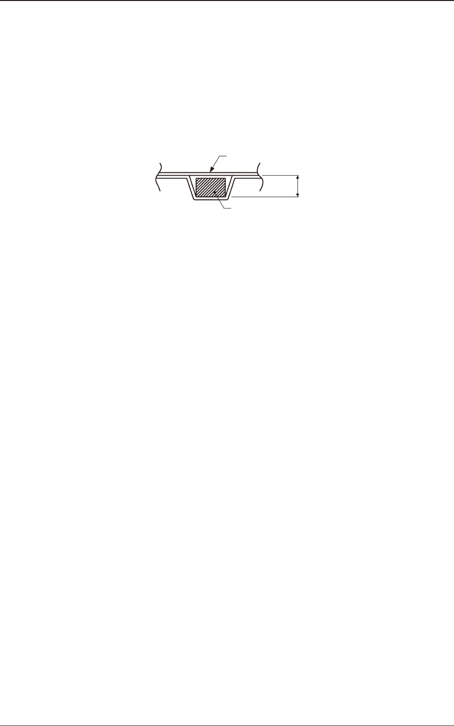
Embossed Taping
"Embossed depth (T
3
) > Component thickness"
Cover Tape
Component
T3
Fig. F7
(g) Shown in column "t" is the gap between the component pick-up and chute
surfaces.
As the gap can be adjusted by the stroke control, set the pick-up level data
in the component library data.
If dimension "t" is big, components may not stay still or may be tilted.
Be sure to adjust the dimension for the appropriate one in the range of
values specied in the table.
(h) The shape of component pick-up surface should be wide and smooth
enough to be picked up by vacuum nozzles.
(i) Cover tapes sometimes become thicker than expected due to leafy and
uffy leftovers produced through the production process.
However, the overall thickness should not exceed the value described as
"T
2
" in the table.
1504-001
6.3 Referential Dimension for Taping
OM-1833
6-6
7. Reference Taping Specications
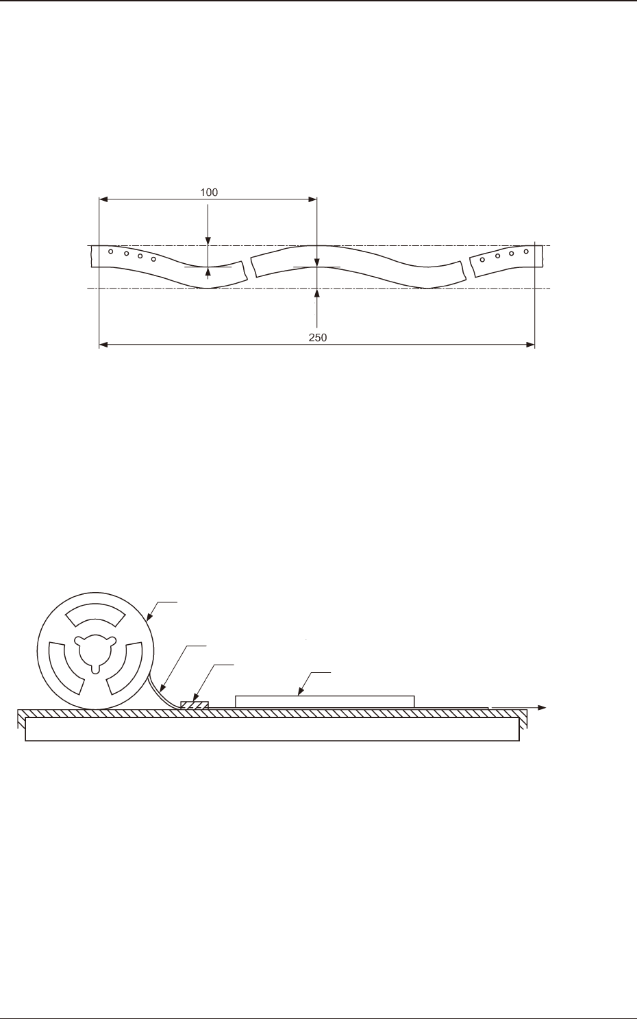
7.1 Allowable Limit of Edge Waving of Tape
Allowable limit of edge waving of tape should be or less than 1 mm per 100 mm
through a length of 250 mm as illustrated.
1 or less
1 or less
Unit : mm
Fig. G1 Allowable Limit of Edge Waving of Tape
7.2 Test Method for Edge Waving of Tape
The edge waving of tape shall be tested in such a manner that one end of tape
is xed, the tape is pulled by a force of 1N (102 gf) applied to the other end, a
graduated transparent plastic plate which also serves as a weight is placed on the
tape, and then the waving is measured.
Tape
Reel
Fixed Point
Graduated transparent plastic plate
which also serves as weight
Force of 1N
(102 gf)
Fig. G2 Test Method for Edge Waving of Tape
1504-001
7. Reference Taping Specications
OM-1833
7-1
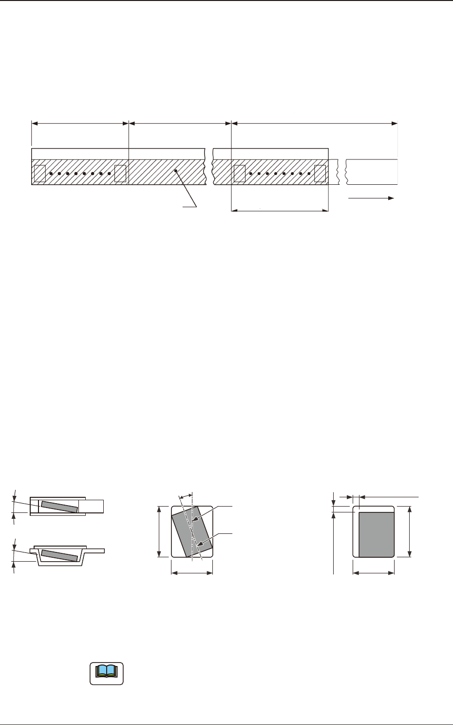
7.3 Leader Section (Tape End Section)
The tape length in the leader section should be 400 mm or more including the
empty component compartment. Such empty component compartment should be
sealed with a cover tape for 100 mm or more.
Trailer (160 mm min.)
(400mm or less)
Portion Equipped with Surface
Mounting Component
Leader (400 mm min.)
Cover Tape
Empty Component
Compartment
Empty Component
Compartment
(100 mm min. Seal)
Direction of Unreeling
Fig. G3
7.4 Trailer Section (Tape Trailer Section)
The tape length of the trailer section, including the embossed or square punched
hole carrier tape that does not contain components, should be greater than 160 mm
and less than 400 mm.
The empty component compartment should be sealed with a cover tape.
The last portion of carrier tape shall release from the reel hub.
7.5 Position of Taped Component
B
0
Center Line of
Component Compartment
Center Line of
Component
(Note)
20° or less (tape width 8 mm)
Top ViewSide Sectional View or
Front Sectional View
Component Revolution in
Horizontal Direction
Component Inclination
10° or less10° or less
B0
A0
(Note)
0.5 mm or less
(Note)
0.5 mm or less
Top View
Component Bias in
Horizontal Direction
A0
Fig. G4
Note
When the direction of a component is changed in the square punched hole or
embossed tape hole, the component can not be picked up easily. In such case,
keep an appropriate clearance around the component in the hole.
1504-001
7.3 Leader Section (Tape End Section)
OM-1833
7-2