OM-1833-001w_SL.pdf - 第96页
1504-001 OM-1833 5-24
1504-001
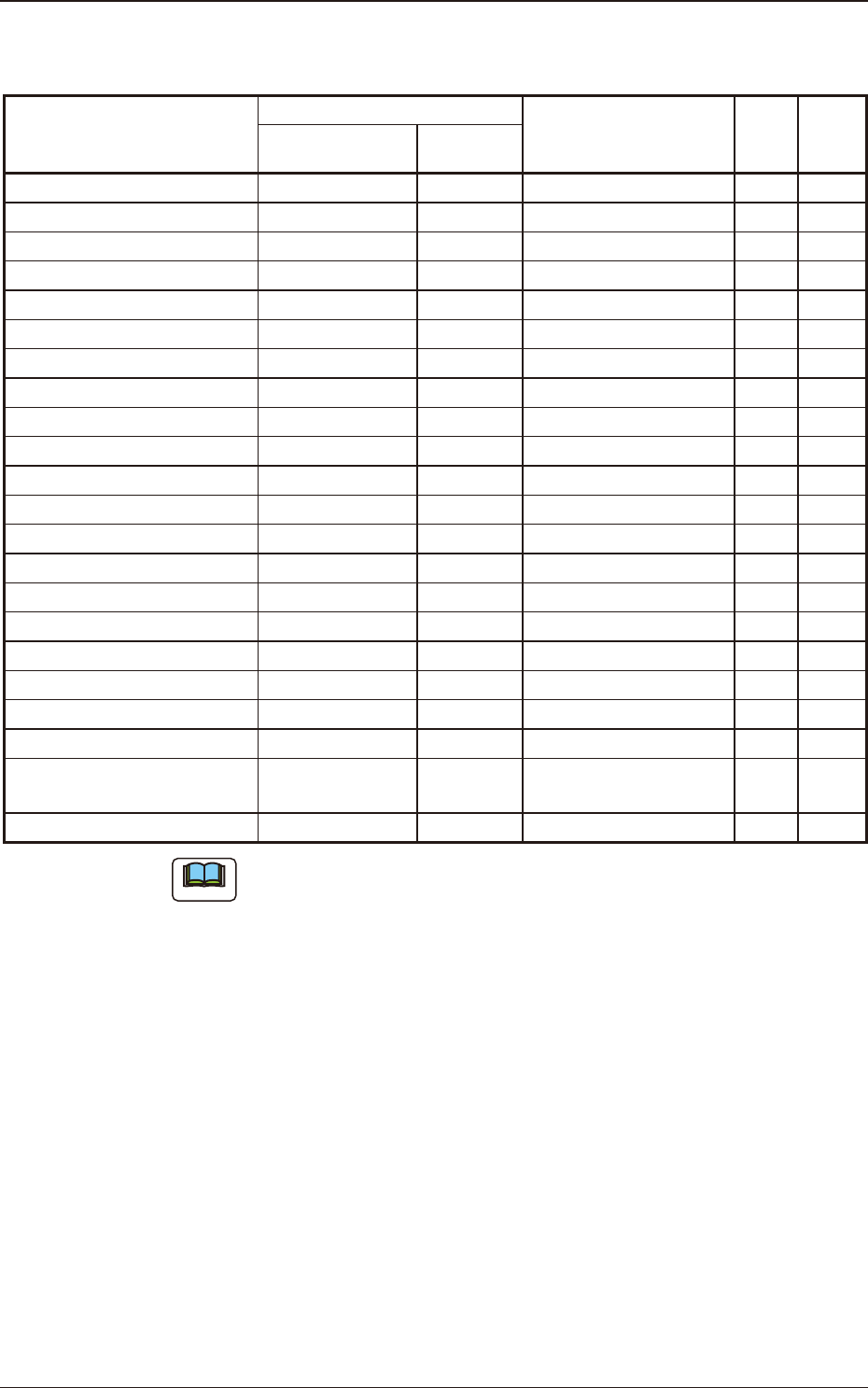
SL-48088D Maintenance Component List
Table E8
Component Name
PART No.
PART NAME Q'ty
Recom-
mended
Years
Yamaha
Hitachi
Table Processing Section(LL) KYE-MCE0F-00 0988A81E CUTTER_BASE(LL) 2 2
Worm Wheel 1ASSY KYE-MCB2F-00 0988030Z ASSY_WHEEL 2 4
Worm Wheel 2ASSY KYE-MCB2K-00 09880A01 ASSY_WHEEL2 2 4
Sprocket 3ASSY KYE-MCB0U-00 09880313 ASSY_SPROCKET3 2 4
Loading Motor KYE-MCB32-00 0988A15G DC_MOTER 2 3
Loading Spur Gears KYE-MCB30-00 0988A153 GEAR 2 3
Timing Belt KYD-MC13V-00 223L0270 BELT_TIMING 2 4
Front End Guide KYE-MCB0G-00 0988A72E GUIDE 1 -
Cover(LA) KYE-MCB0A-00 0988A145 COVER(LA) 1 -
Cover(LB) KYE-MCB15-00 0988A146 COVER(LB) 1 -
Cover(LC) KYE-MCB16-00 0988A147 COVER(LC) 1 -
Cover(LD) KYE-MCB17-00 0988A148 COVER(LD) 1 -
Cover(RA) KYE-MCB18-00 0988A149 COVER(RA) 1 -
Cover(RB) KYE-MCB19-00 0988A14A COVER(RB) 1 -
Cover(RC) ASSY KYE-MCB25-00 0988030G ASSY_COVER(RC) 1 -
Sensor Lever 1 KYE-MCB31-00 0988A15F LEVER1 2 -
Sensor Lever 2 KYE-MCB34-00 0988A163 LEVER2 2 -
Suppressor ASSY(L) KYE-MCE0D-00 0988A19Y ASSY_COVER(L) 1 -
SuppressorASSY(R) KYE-MCE09-00 0988A19Z ASSY_COVER(R) 1 -
Magnetic Plate KYE-MCE08-00 09880A0G ASSY_MP(LL) 2 -
Loading Suppressor
Assembly ASSY
KYE-MCB0V-00 09880A04 ASSY_SUPPRESS0R 2 -
Operation Panel KYD-MC121-00 4B111602 PCB_MOUNT 1 -
Note
The numbers entitled "Recommended Years" indicate the referential values.
5.6 Maintenance Component List
OM-1833
5-23

1504-001
OM-1833
5-24

6. Specications of Tape Feeders
6.1 Specications of 8 mm Dual Tape Feeder
Table F1
SL Feeder
Model No.
Tape Width ×
Feed Pitch
(mm)
Type of Tape
Diameter ×
Reel Outer
Width (mm)
Chute
Height
(mm)
External dimensions
of Applicable
components
(mm)
Note (a)
Remarks
Distance between
fused bands of
Cover Tape (mm)
Applicable
components
SL-48085
8 × 1 Paper
Φ180
×
14.4
104
0.35 < X <= 1.20
0.15 < Y <= 1.00
1.1 or more
0402C/R,
0603C/R
• For 1 mm pitch tape
• Bar code label color:
Light blue and White
• Cover tape disposal type:
SL-48CB5
1.3 or more 1005C/R
8 × 2
Paper,
Embossed
1.1 or more
0402C/R,
0603C/R/DI
1.3 or more 1005C/R
SL-48086
8 x 2, 4 Paper
0.65 < X <= 1.80
0.35 < Y <= 3.00
1.9 or more 1005 C/R
• Bar code label color:
Yellow and White
• Cover tape disposal type:
SL-48CB6
2.1 or more 1608 C/R
8 x 2, 4 Embossed 1.9 or more
1006DI
1208DI
1208TR
1408TR
1608TR
SL-48087
8 × 4 Paper
1.40 < X <= 2.10
0.35 < Y <= 3.00
2.3 or more
1608C/R
2012C/R
• Bar code label color:
Pink and White
• Cover tape disposal type:
SL-48CB7
8 × 2, 4 Embossed
1208DI
1608TR
SL-48088
8 × 4 Paper
2.10 < X <= 3.40
0.35 < Y <= 3.00
3.6 or more
3216C/R
• Bar code label color:
White
• Cover tape disposal type:
SL-48CB8
8 × 4 Embossed
1713DI
2916DI
2012TR
2915TR
Note
(a) The sizes of the components entitled "Referential Components" differ
depending on the component makers.The components are shown as types
for your reference.
Distance between fused bands of Cover Tape
This is the distance between two fused bands which xes the cover
tape onto the carrier tape, and the bands are made next to both sides
the pockets for components.
(Fused width depends on component dimensions.)
W
i
d
t
h
o
f
C
o
v
e
r
T
a
p
e
W
i
d
t
h
o
f
C
o
v
e
r
T
a
p
e
D
i
s
t
a
n
c
e
b
e
t
w
e
e
n
f
u
s
e
d
b
a
n
d
s
D
i
s
t
a
n
c
e
b
e
t
w
e
e
n
f
u
s
e
d
b
a
n
d
s
D
i
s
t
a
n
c
e
b
e
t
w
e
e
n
f
u
s
e
d
b
a
n
d
s
W
i
d
t
h
o
f
C
o
v
e
r
T
a
p
e
Fig. 1
(b) Splicing tape cannot be used. If splicing tape is used, a pickup malfunction
may occur.
(c) The joint of the spliced section cannot be detected.
1504-001
6. Specications of Tape Feeders
OM-1833
6-1