OM-1833-001w_SL.pdf - 第99页
6.3 Referential Dimension for T aping 6.3.1 Referential Dimension for T aping (8 mm Paper) Rectangle Hole Punched Carrier T ype T aping Rectangle Hole Punched Carrier T ype T aping Cover T ape T aped Component Direction …

6.2 Tape loading time and tape automatic exchange time
Table F2
No Item Specication Content
1 Tape loading time
Approximately 6
seconds
The time required from when rotating operation begins after
the tip of the tape is set in the appropriate position of the feeder,
until the tape has been conveyed to the pickup position.
* The required time will differ slightly depending on differences
in the type and feed pitch of the tape.
2
Tape automatic
exchange time
Approximately 8
seconds
The time required for the next-supplied tape to be automatically
exchanged when the previous tape has run out of components
during production operation.
* This includes the time for ejecting the previous tape that has
run out of components.
Note
Pickup from the corresponding lane is not possible while tape switching
is being performed.
For this reason, we recommend that you also use the feeder alternate function or
the postponed recovery function.
If the postponed recovery function is used, operation will skip component
pickup from the corresponding lane while pickup is impossible due to tape
switching, and will continue mounting other components.
Unlike conventional feeders, the SL feeders will automatically switch to the next
tape if components run out and the following resupply tape has been set; thus,
the temporarily-skipped component can be picked up last, and production can
continue without interruption.
6.2 Tape loading time and tape automatic exchange time
OM-1833
6-2
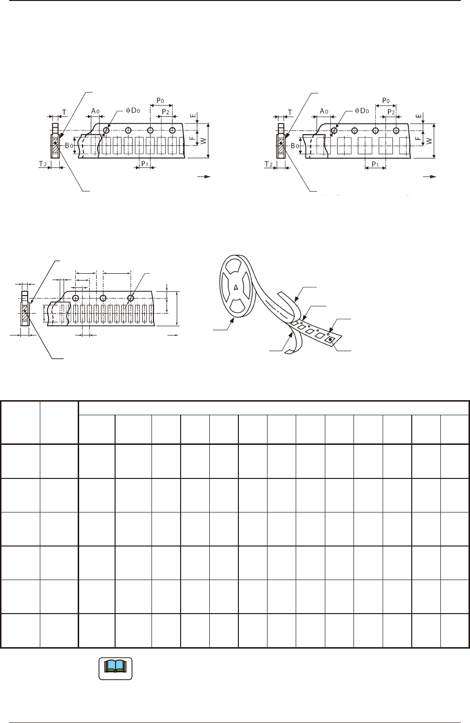
6.3 Referential Dimension for Taping
6.3.1 Referential Dimension for Taping (8 mm Paper)
Rectangle Hole Punched Carrier Type Taping Rectangle Hole Punched Carrier Type Taping
Cover Tape
Taped Component
Direction of Unreeling
(Sprocket Hole)
Cover Tape
Taped Component
(Sprocket Hole)
Direction of Unreeling
Fig. F1 Rectangle Hole Pitch (2 mm) Fig. F2 Rectangle Hole Pitch (4 mm)
Rectangle Hole Punched Carrier Type Taping
P
2
P
1
T
2
T
A
0
B
0
P
0
φ
D
0
(Sprocket
Hole)
Direction of Unreeling
Taped Component
Cover Tape
F E
W
P
3
P
4
Cover Tape
Rectangle Punched Carrier Tape
Sprocket Hole
Rectangle Hole Component
Compartment
Reel
Bottom Cover Tape
Fig. F3 Rectangle Hole Pitch (1 mm) Fig. F3-1
Table F3
Cover Tape
Processing
Section
Type
Tape Width
×
Feed Pitch
(mm)
Reference taping dimensions (mm)
A
0
B
0
W F E P
1
P
2
P
3
P
4
P
0
D
0
T T
2
S 8×1
More than
0.2 to 0.6
or less
More than
0.4 to 1.2
or less
8.0
±
0.1
3.5
±
0.05
1.75
±
0.1
1.0
±
0.05
1.0
±
0.05
-2.0
±
0.05
3.0
±
0.05-
4.0
±
0.05
φ
1.5
+
0.1
0
0.16
or more
0.6
or less
0.6
or less
S 8×2
More than
0.2 to 0.6
or less
More than
0.4 to 1.2
or less
8.0
±
0.1
3.5
±
0.05
1.75
±
0.1
2.0
±
0.05
2.0
±
0.05
- -
4.0
±
0.05
φ
1.5
+
0.1
0
0.16
or more
0.7
or less
0.7
or less
M 8×2
More than
0.4 to 0.8
or less
More than
0.7 to 1.7
or less
8.0
±
0.1
3.5
±
0.05
1.75
±
0.1
2.0
±
0.05
2.0
±
0.05
- -
4.0
±
0.05
φ
1.5
+
0.1
0
0.16
or more
1.1
or less
0.7
or less
M 8×4
More than
0.8 to 3.4
or less
More than
1.7 to 2.0
or less
8.0
±
0.1
3.5
±
0.05
1.75
±
0.1
4.0
±
0.05
2.0
±
0.05
- -
4.0
±
0.05
φ
1.5
+
0.1
0
0.16
or more
1.1
or less
1.1
or less
L 8×4
More than
0.8 to 3.4
or less
More than
1.7 to 2.2
or less
8.0
±
0.1
3.5
±
0.05
1.75
±
0.1
4.0
±
0.05
2.0
±
0.05
- -
4.0
±
0.05
φ
1.5
+
0.1
0
0.16
or more
1.1
or less
1.1
or less
LL 8×4
More than
1.6 to 3.4
or less
More than
2.2 to 3.7
or less
8.0
±
0.1
3.5
±
0.05
1.75
±
0.1
4.0
±
0.05
2.0
±
0.05
- -
4.0
±
0.05
φ
1.5
+
0.1
0
0.16
or more
1.1
or less
0.8
or less
Note
(a) A
0
×
B
0
stands for the rectangle hole size on the tape.
The clearance between a rectangle hole and a component affects the pick-
up rate.Use the taping component with appropriate clearance specications.
1504-001
6.3 Referential Dimension for Taping
OM-1833
6-3
(b) The above specications do not imply any guarantee of pick-up rate, etc.
The pick-up rate varies depending on how the main machine is adjusted
and the combination of the main machine and the tape feeders.
(c) The clearance between the centerlines of the cavity and the sprocket hole
should be 0.05 mm or less.
(d) 10 pitches cumulative tolerance P
0
should be ± 0.2 mm.
(e) The cover tape should run smoothly along the sprocket holes.
The edges of the cover tape should be aligned with the carrier tape (taping).
The thickness of the cover tape should be 0.07 mm or less (including waste
paper).
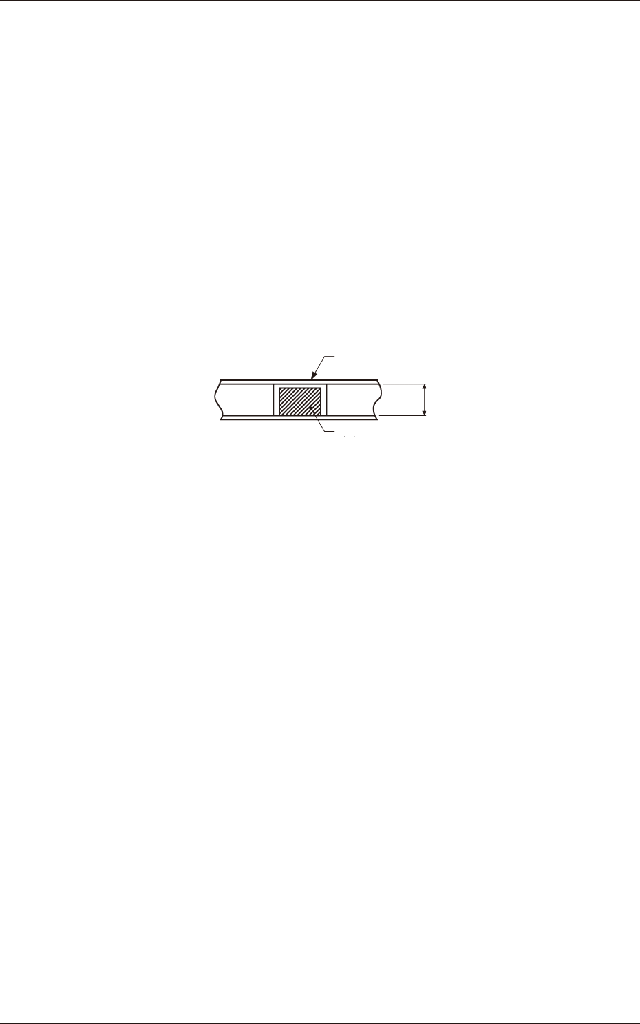
(f) Use a taping on condition that the component itself or its electrical contact
is not protruded from the upper surface of tape.
Paper Taping
"Tape thickness (T) > Component thickness"
Cover Tape
Component
T
Fig. F4
(g) The shape of component pick-up surface should be wide and smooth
enough to be picked up by vacuum nozzles.
(h) Cover tapes sometimes become thicker than expected due to leafy and
uffy leftovers produced through the production process.
However, the overall thickness should not exceed the value described as
"T
2
" in the table.
1504-001
6.3 Referential Dimension for Taping
OM-1833
6-4