OM-1833-001w_SL.pdf - 第84页
1504-001 5.5.1.2 Left Side Cover #1 Attachment Procedure Procedure (1) Push the claws of the cover LA into the slits in the frame #1. Fig. E12 (2) Slide the cover LA in the arrow direction (to the right) to set the claws…
5.5 Maintenance Method
5.5.1 Cover Removal and Attachment
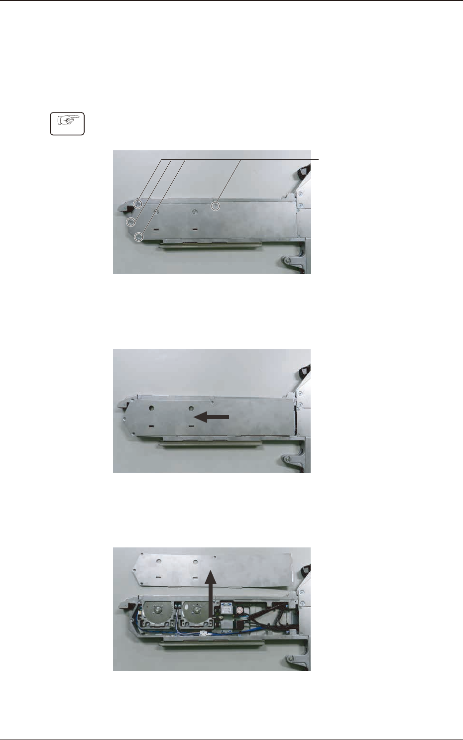
5.5.1.1 Cover LA Removal Procedure
Procedure
(1) Remove the countersunk set screw for xing the cover LA (4 locations).
Screw Hole
(4 locations)
Fig. E9
(2) Slide he cover LA in the arrow direction.
Fig. E10
(3) Then slide the cover LA in the arrow direction (upper) to remove.
Fig. E11
1504-001
5.5 Maintenance Method
OM-1833
5-11
1504-001
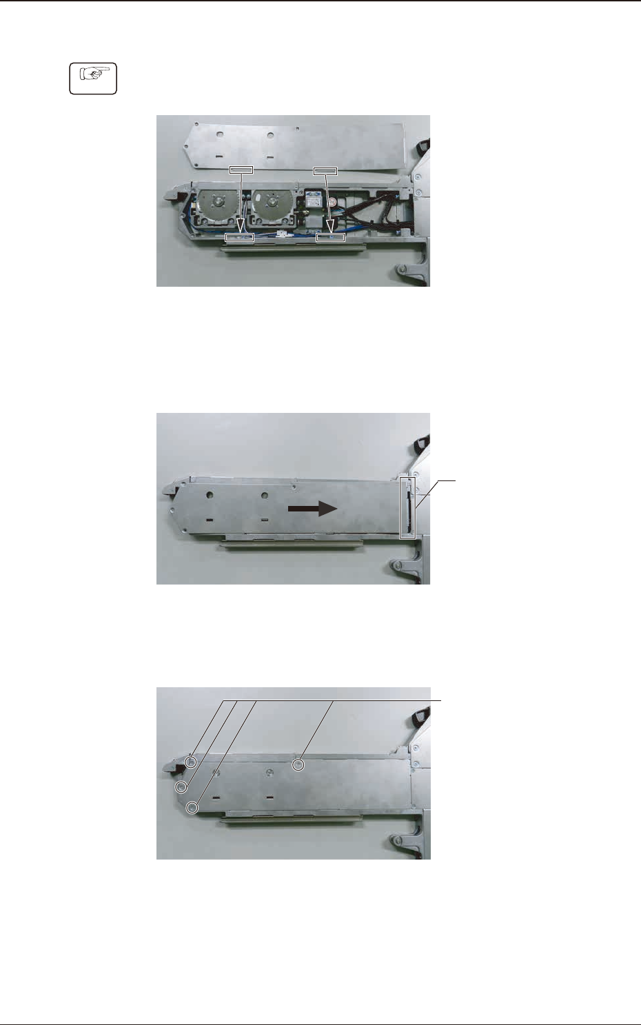
5.5.1.2 Left Side Cover #1 Attachment Procedure
Procedure
(1) Push the claws of the cover LA into the slits in the frame #1.
Fig. E12
(2) Slide the cover LA in the arrow direction (to the right) to set the claws under
the other cover.
Set the
claws under it.
Fig. E13
(3) Attach the countersunk screws to x the cover LA (4 locations).
Screw Hole
(4 locations)
Fig. E14
5.5 Maintenance Method
OM-1833
5-12
1504-001
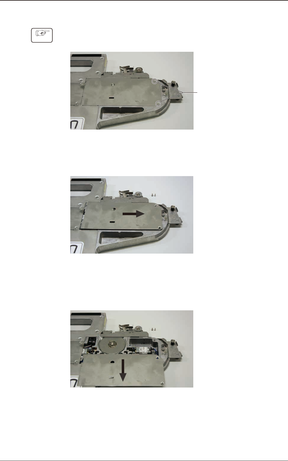
5.5.1.3 Cover LD Removal Procedure
Procedure
(1) Remove the countersunk screws xing the cover LD.
Countersunk Screw
(2 locations)
Fig. E15
(2) Slide the cover LD in the arrow direction (to the right).
Fig. E16
(3) Then, slide the cover LD in the arrow direction (lower) to remove the cover
LD.
Fig. E17
5.5 Maintenance Method
OM-1833
5-13