OM-1833-001w_SL.pdf - 第51页
Note (a) The partition panel pitch (bay) should be 21 mm in the reel holding section and the thickness of the partition panel should be 0.8 mm. (b) When 2 pitches or more are used, remove the partition panel. Notice When…
3.1 Tape Feeder Attachment Procedure
CAUTION
Do not drop the tape feeder, when attaching or
detaching.
Some tape feeder models are rather heavy.
In the case that the feeder is removed with one hand, your
hand might not be able to support the feeder weight when
it is removed from the base, which might cause a fall of
the feeder.
Falling of a tape feeder might cause an injury on your feet
or damage to the feeder.
Hold such feeder with your both hands one by one and
take care not to drop it.
Procedure
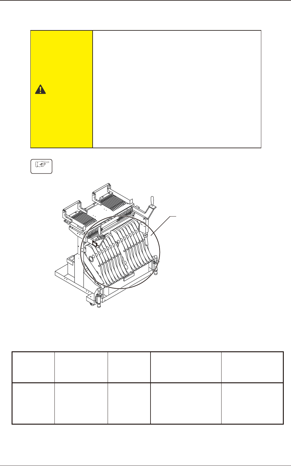
(1) Set the reel onto the reel receiving bay in the reel holding section on the bank
feeder change cart.
Reel Holding Section
Fig. C1
Feeder Size and Conditions
Table C1
Model
No. of Feeder
Bases to be
mounted (pcs.)
Feeder
Width
(mm)
Max. Reel Width
(mm)
Pitch to be used
SL-48085
SL-48086
SL-48087
SL-48088
20 20.2 14.4 1
1504-001
3.1 Tape Feeder Attachment Procedure
OM-1833
3-2
Note
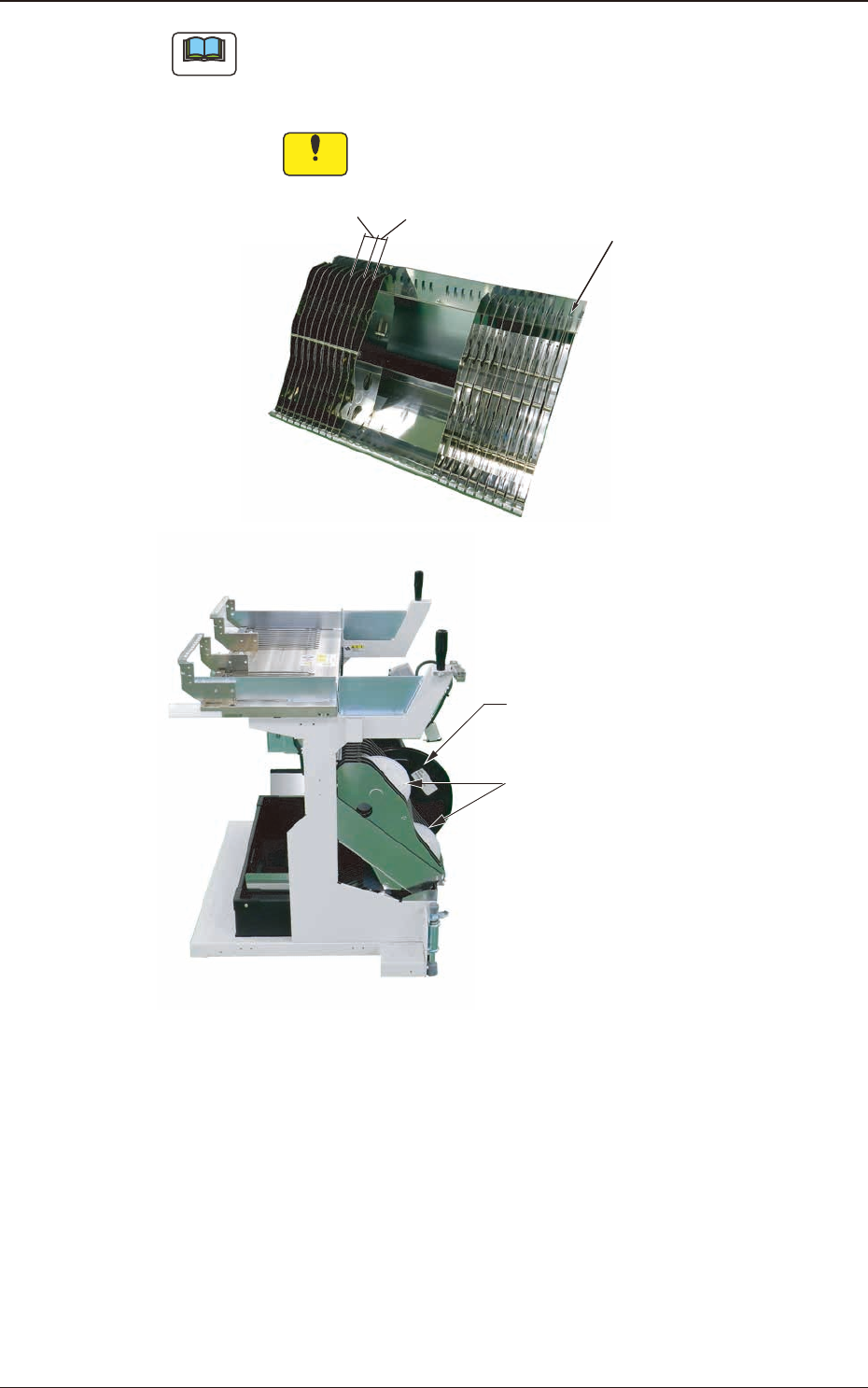
(a) The partition panel pitch (bay) should be 21 mm in the reel holding section
and the thickness of the partition panel should be 0.8 mm.
(b) When 2 pitches or more are used, remove the partition panel.
Notice
When removing or setting the partition panel, take care not
to hurt your ngers.
リール保持部
2 Pitch
1 Pitch
Partition Panel
Reel Holding Section
Large Reel Set Position
Small Reel Set Position
Fig. C2
1504-001
3.1 Tape Feeder Attachment Procedure
OM-1833
3-3
(2) Before setting the tape feeder onto the bank feeder change cart, make sure
that there are no such foreign objects as dirt or dust on the feeder base on the
upper section of the cart.
(3) Attach the tape feeder to the feeder base with the specied feeder No..
Notice
•
If the hook section at the end of the tape feeder is bumped, it
will be deformed, and so cause a pick-up error.
Take care not to bump the hook section.
•
Set the tape feeder onto the slot with the correct Fdr. No..
If it is not set correctly, the component might enter the head
section.
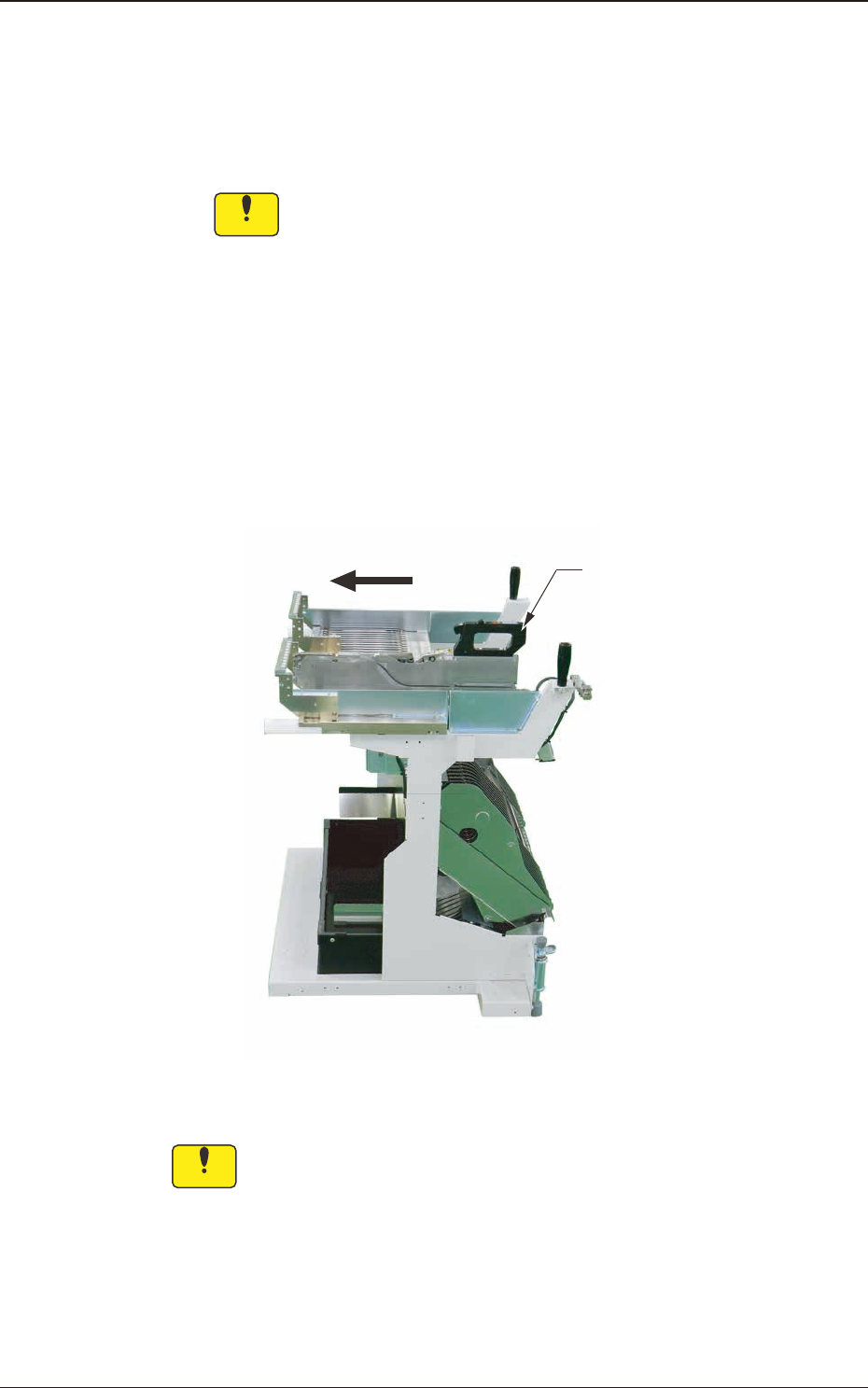
(4) Hold the grip and insert the tape feeder end so that it is aligned with the
feeder base rail.
Then push the rear of the grip forward and make sure that the tape feeder has
been securely set.
Grip
Fig. C3
Notice
Set the tape feeder securely onto the rail of the feeder base.
1504-001
3.1 Tape Feeder Attachment Procedure
OM-1833
3-4