OM-1833-001w_SL.pdf - 第108页
1504-001 OM-1833 8-2
1504-001 (3M988W*M---0001)
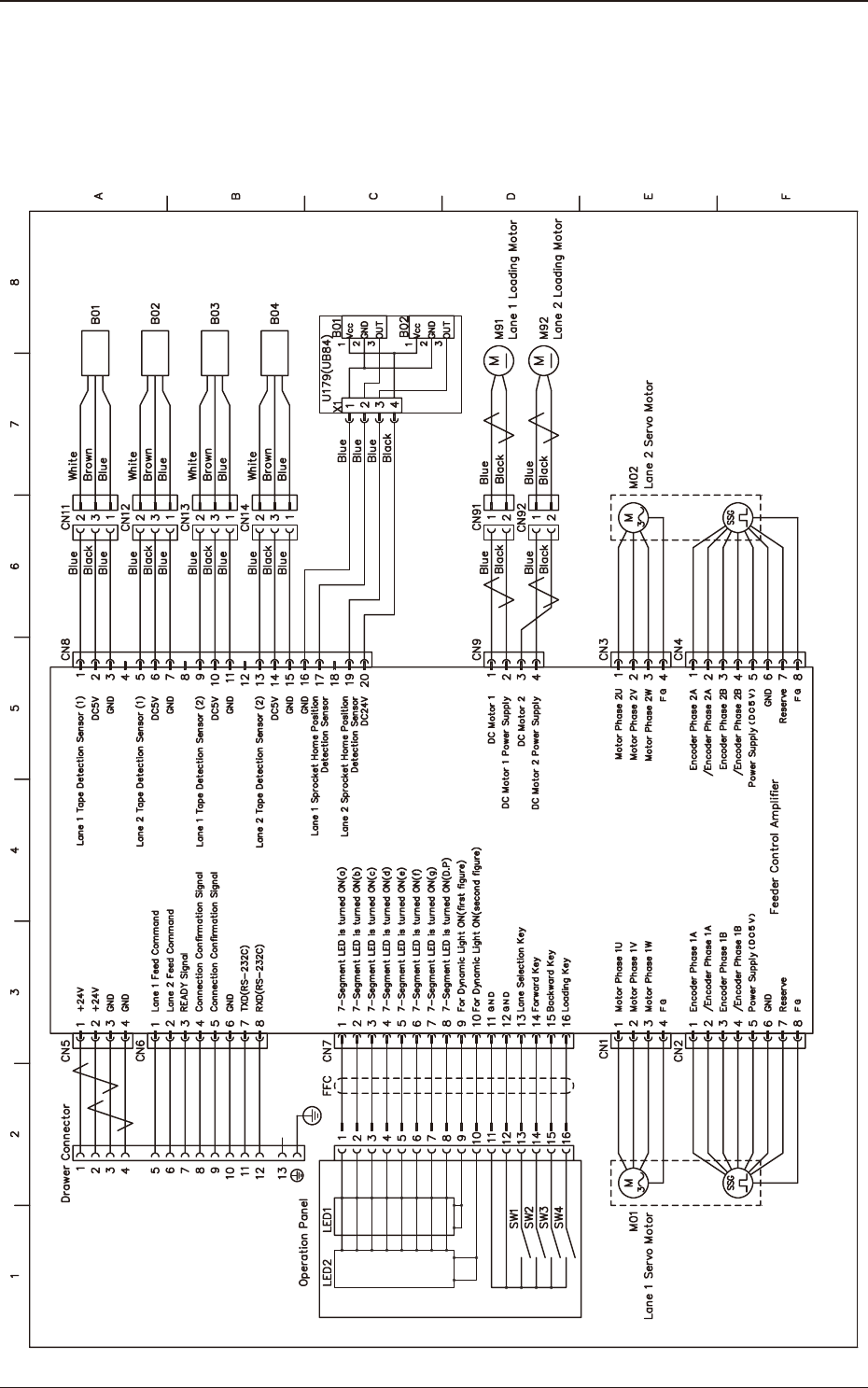
8. Electrical Circuit Diagrams
8.1 Feeder Control Circuit Diagram
(SL-48085/48086/48087/48088)
8. Electrical Circuit Diagrams
OM-1833
8-1

1504-001
OM-1833
8-2
9. Troubleshooting
The main troubleshooting during the tape feeder operation is described here.
In the event of trouble, con rm in which section the trouble is caused and set it
right.
9.1 Component Pick-up Error
Remedy
: Unload the tape and process the tape end correctly, and then load it.
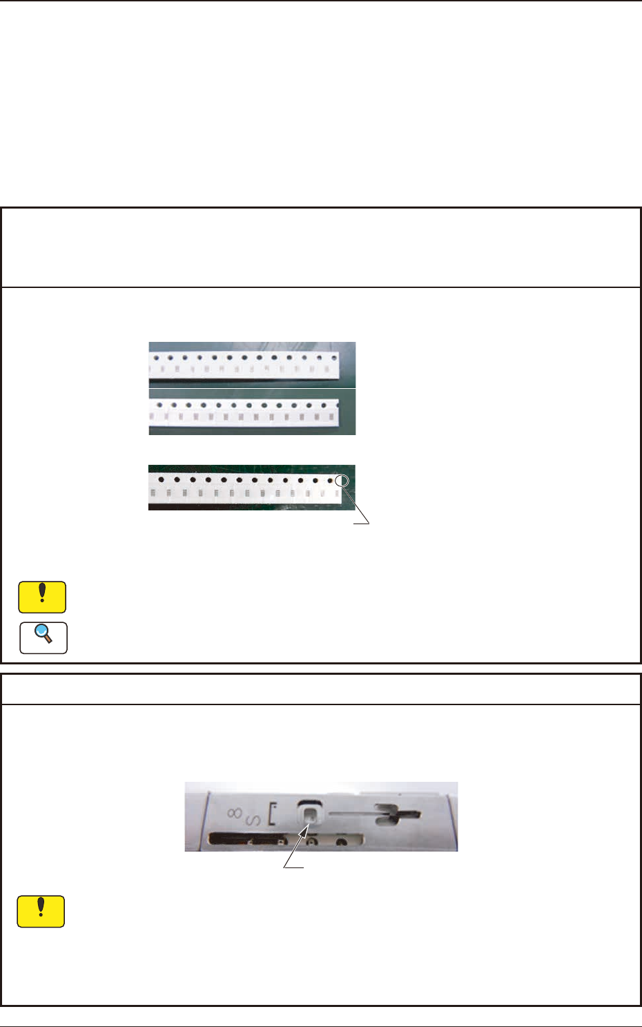
Cut the tape at the position to the left end
of the next sprocket hole as shown in the
above figure.
NG
OK
If the component center is not aligned with the pick-up position, then the pick-up cannot
proceed correctly.
Refer to "2.4 Tape End Processing Procedure" for the tape end processing procedure.
Cause : Pick-up position is not correct (pitch deviated)
In the tape end processing in the tape loading operation, if the tape is not cut at the cor-
rect position, the feeding position pitch would be deviated.
Remedy
: Adjust the pick-up position by using the feeder adjusting jig JG-0209
(Purchase separately).
Pick-up Position
If the component center is not aligned with the pick-up position, then the pick-up cannot
proceed correctly.
Cause : Error in Pick-up Position
9. Troubleshooting
Reference
Notice
Notice
1504-001
OM-1833
9-1