OM-1833-001w_SL.pdf - 第89页
1504-001 5.5.3 SL T ape Feeder Oiling 5.5.3.1 Sprocket (1) and Sprocket (2) Oiling Procedure Procedure (1) For sprocket (1) and sprocket (2), grease can be applied directly from the oiling slit on the right side of the f…
1504-001
5.5.2.2 PCB BOX Cover Attachment Procedure
Procedure
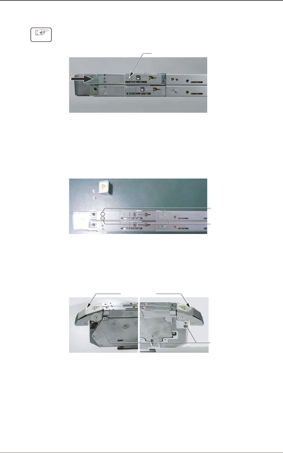
(1) Moving the suppressor up, pass the cutter base under the suppressor and
slide it in the arrow direction (to the left).
Cutter Base
Fig. E24
(2) Position the cutter base so that the projection on the cutter base is aligned
with the suppressor hole position. Fix the cutter base onto the suppressor
using the No. 0 round head screw (2 locations).
No. 0 Round
Head Screw
Positioning
(2 locations)
Fig. E25
(3) Attach the tape guide to the frame #1 front end and x it using countersunk
screw (2 locations).
Tape Guid
Countersunk Screw
(2 locations)
Fig. E26
5.5 Maintenance Method
OM-1833
5-16
1504-001
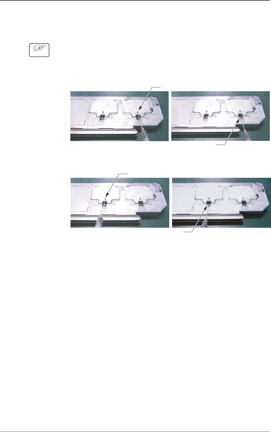
5.5.3 SL Tape Feeder Oiling
5.5.3.1 Sprocket (1) and Sprocket (2) Oiling Procedure
Procedure
(1) For sprocket (1) and sprocket (2), grease can be applied directly from the
oiling slit on the right side of the frame #1 using the dedicated oiling jig.
Also, the grease amount applied to each section should be 0.2 ml (two
divisions in the oiling jig).
Sprocket 1
Sprocket 2
Oiling Slit on the side of the Lane #1 (Upper Side)
Oiling Slit on the side of the Lane #2 (Lower Side)
Oiling Slit on the side of the Lane #1 (Upper Side)
Oiling Slit on the side of the Lane #2 (Lower Side)
Fig. E27
7.5 Maintenance Method
OM-1833
5-17
1504-001
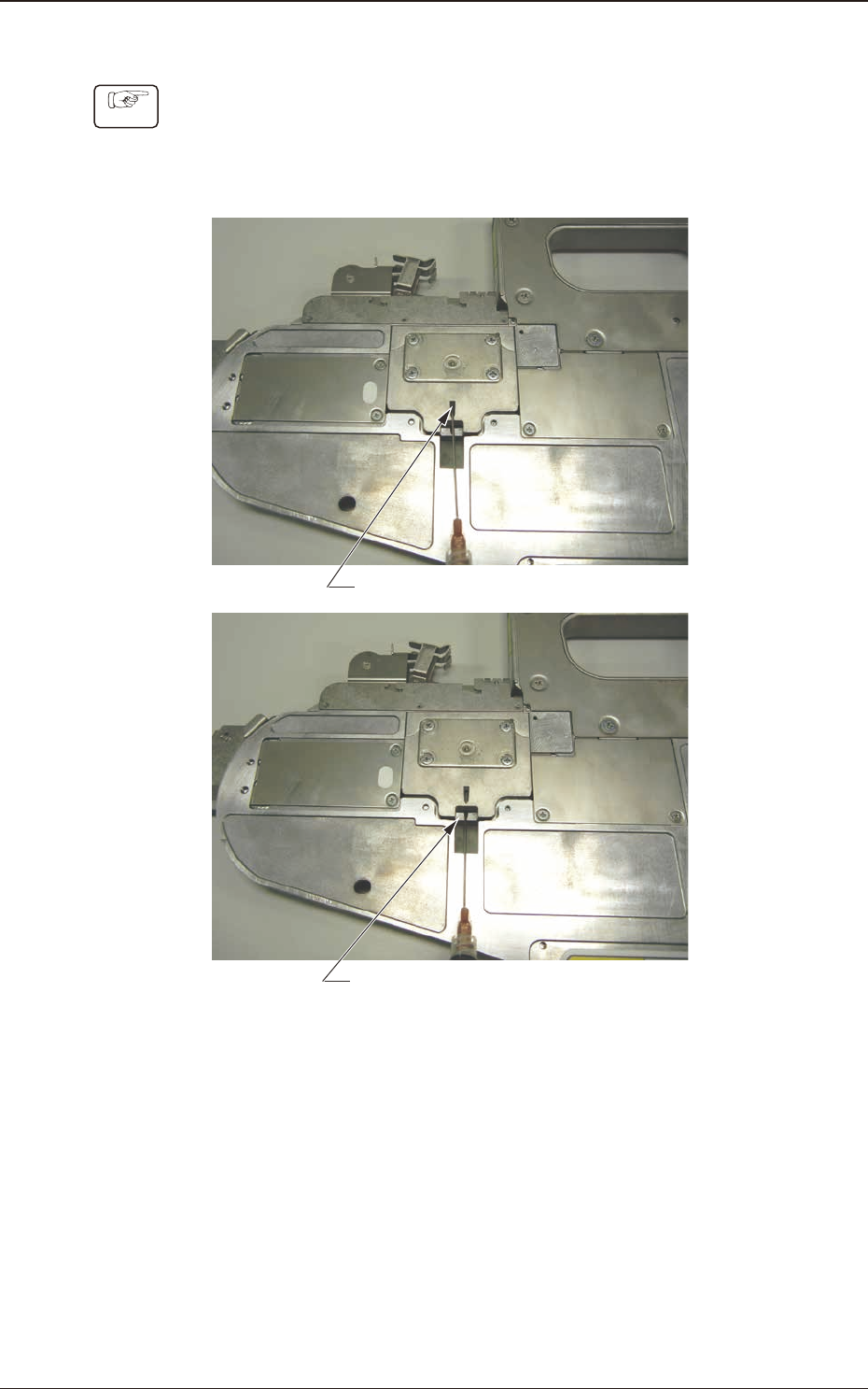
5.5.3.2 Sprocket (3) Oiling Procedure
Procedure
(1) For the sprocket (3), grease can be applied directly from the oiling slit on the
right side of the frame #2 using the dedicated oiling jig.
Also, the grease amount applied to each section should be 0.2 ml (two
divisions in the oiling jig).
Oiling Slit on the side of the Lane #1 (Upper Side)
Oiling Slit on the side of the Lane #2 (Lower Side)
Fig. E28
5.5 Maintenance Method
OM-1833
5-18