OM-1833-001w_SL.pdf - 第33页
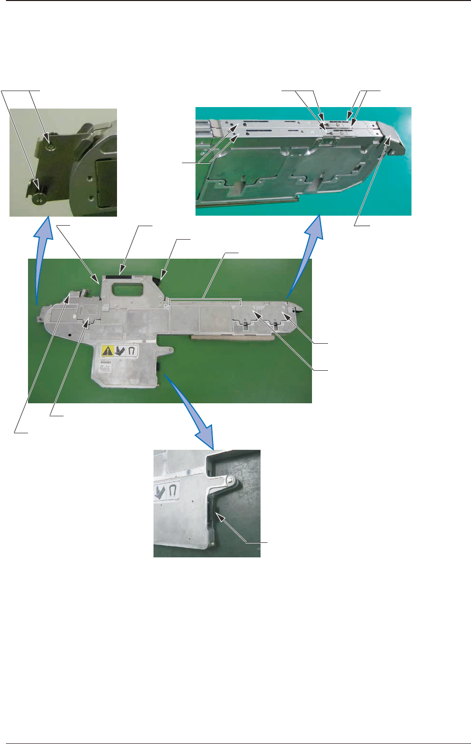
1504-001 1.5 Name and Function of Each Section It is described in SL-48085 (8 mm Dual Tape Feeder) [1] Operation Panel [3] Clamp Release Lever [5] Chute [7] Sprocket (2) [6] Sprocket (1) [14] Connector [13] Tape Outlet G…
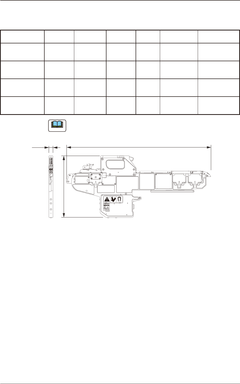
1.4 Types Tape Feeders
Table A3
Tape Feeder
Tape Width ×
Feed Pitch (mm)
Cover Tape
Processing
Section Type
Types of
Tape
Mass
(kg)
Power Supply
Barcode
Label Color
SL-48085
8 mm Dual
Tape Feeder
(Note)
8 × 1, 2 S
Paper
Embossed
3.5 DC24V
±
10% Blue + White
SL-48086
8 mm Dual
Tape Feeder
8 × 2, 4 M
Paper
Embossed
3.5 DC24V
±
10% Yellow + White
SL-48087
8 mm Dual
Tape Feeder
8 × 2, 4 L
Paper
Embossed
3.5 DC24V
±
10% Pink + White
SL-48088
8 mm Dual
Tape Feeder
8 × 4 LL
Paper
Embossed
3.5 DC24V
±
10% White
Note
SL-48085 is applicable to 1 mm pitch tape.
732
312
20.2
Unit : mm
Fig. A12 8 mm Dual Tape Feeder
1504-001
1.4 Types Tape Feeders
OM-1833
1-12
1504-001
1.5 Name and Function of Each Section
It is described in SL-48085 (8 mm Dual Tape Feeder)
[1] Operation Panel
[3] Clamp Release Lever
[5] Chute
[7] Sprocket (2)
[6] Sprocket (1)
[14] Connector
[13] Tape Outlet Guide
(At the succeeding tape set-up)
[9] Suppressor
[10] Cover Tape
Processing Section
[12] Tape Outlet Guide
[11] Component
Pick-up Section
[2] Barcode
Label
[4] Loading Suppressor
[8] Sprocket (3)
Fig. A23
1.5 Name and Function of Each Section
OM-1833
1-13

1504-001
[1] Operation Panel
This switch panel is used to display tape feeder status or perform the manual
operation.
Reference
Refer to "4. Operation Panel" for details.
[2] Barcode Label
Barcodes are printed for tape feeder model, serial No. and ACV system.
[3] Clamp Release Lever
This button is pressed when the tape feeder is removed from the bank feeder
change cart.
[4] Loading Suppressor
When the tape is to be loaded automatically, it is used to push the tape
against the chute to maintain a stable tape feeding.
This unit is attached on both the left and right lanes.
When a tape to be setup automatically is inserted, slide the loading
suppressor in this side to expand the tape insertion opening. After the tape is
inserted to the specied position, slide it with the loading suppressor pressed
down in the front direction.
[5] Chute
This is the tape traveling surface.
Make sure that there is no alien substance (chip component or debris)
attached on it.
[6] Sprocket (1)
The sprocket teeth are engaged with the perforations on the tape to feed the
tape according to the feeding pitch.
[7] Sprocket (2)
This sprocket carries the tape end into the cover tape processing section in
the tape loading operation.
It is driven using the servo-motor common to sprocket (1), and controls
acceleration, deceleration or speed control of tape feeding.
[8] Sprocket (3)
This sprocket carries the tape inserted into the guide opening into the feeder.
The tooth shape of this sprocket is different from those of the sprocket (1) or
(2) so as not to damage the perforations on the tape. It is driven using the DC
motor.
1.5 Name and Function of Each Section
OM-1833
1-14