Maintenance Manual.pdf - 第143页
RL131 MAINTENANCE MANUAL 7.3 PCB T ransfer Unit DA8MEC-Z4-000-A 0 7.3-6
RL131
MAINTENANCE MANUAL
7.3 PCB Transfer Unit
DA8MEC-Z4-000-A0
7.3-5
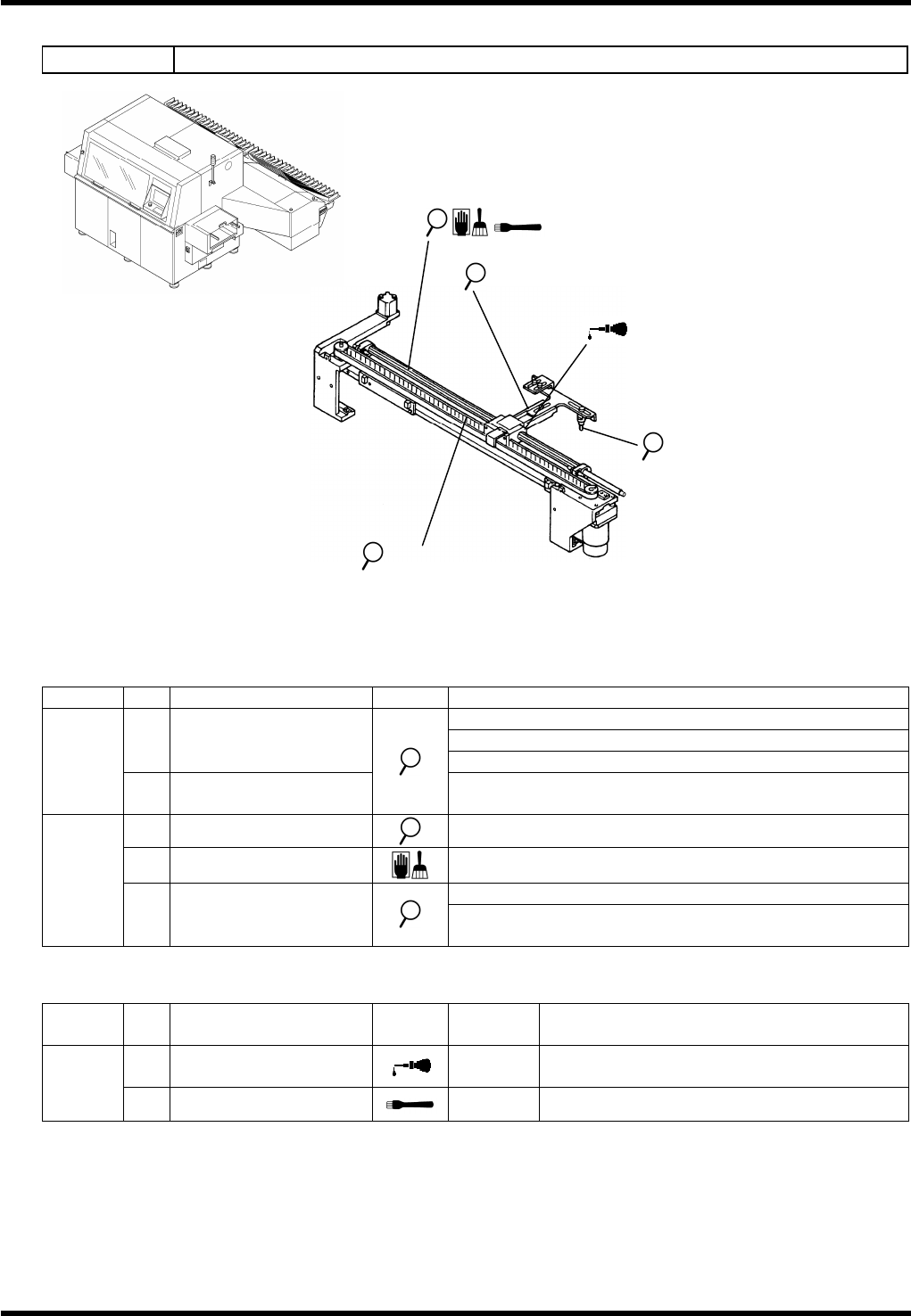
7.3.5 PCB Transfer Unit
Unit No. N610060945AA
Inspection
Period
No.
Item Task Description
Make sure that the lever moves up/down smoothly.
Make sure that the lever slides smoothly.
a.
Lever
Make sure that the lever moves lightly at the support.
Daily
b.
Transfer pin
Make sure that the transfer pin is inserted into the PCB
hole correctly.
c.
Belt
Make sure that the belt is not worn.
d.
Shaft
Sliding surface: Remove dirt or dust.
Make sure that the transfer pin claw is not loosened.
Weekly
e.
Transfer pin
Make sure that the transfer pin claw is not damaged or
deformed.
Oiling
Period
No.
Item Task
Oiling
volume
Description
1.
Lever support
1 to 2
drops
3
months
2.
Shaft
0.25 cm
3
Position: Sliding surface
1. Lever support
b. / e. Transfer pin
d. / 2. Shaft
a. Lever
c. Belt

RL131
MAINTENANCE MANUAL
7.3 PCB Transfer Unit
DA8MEC-Z4-000-A0
7.3-6
RL131
MAINTENANCE MANUAL
7.4 Insertion Head
DA8MEC-Z1-M00-A0
7.4-1
7.4. Insertion Head
DA8MEC-Z1-M00-A0
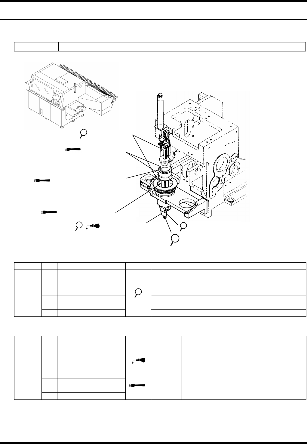
7.4.1 Insertion Head
Unit No. N610067465AA
Inspection
Period
No.
Item Task Description
a.
Insertion chuck Make sure that insertion chunk opens/closes smoothly.
b.
Insertion pusher rubber
Make sure that the insertion pusher rubber is not worn
or damaged.
c.
Insertion pusher
Make sure that the insertion pusher smoothly slides
vertically.
Daily
d.
Sensor
Wipe off any dust or dirt at the edge of the sensor.
Oiling
Period
No.
Item Task
Oiling
volume
Description
Weekly
1.
Insertion chuck support
shaft
1 drop to
each
bush
Apply oil to the support shaft. (Apply oil as
needed if the unit does not open/lose
smoothly after daily inspection.)
2.
Shifter A, B
3.
Seam between shifter
A and B
Monthly
4.
Ball spline
0.5cm
3
Remove all dirt adhering on the surface
completely and apply a thin coat of grease.
=REMARKS=
Keep the sensors, insertion chuck rubber and insertion pusher rubber free from oil or grease.
2. Shifter A, B
b.
Insertion pusher rubber
c. Insertion pusher
3. Seam between shifter A
and B
4. Ball spline
a. / 1. Insertion chuck
d. LM guide (X)