Maintenance Manual.pdf - 第38页
RL131 MAINTENANCE MANUAL 2.3 Maintenanc e Function DA8MEC-10-030- A0 2.3-5 2.3.4 Op erational Re strictions Inhibited Operation s (Cannot be S topped Unle ss Operating Intenti onall y) Origin return of all axes Axi…
RL131
MAINTENANCE MANUAL
2.3 Maintenance Function
DA8MEC-10-030-A0
2.3-4
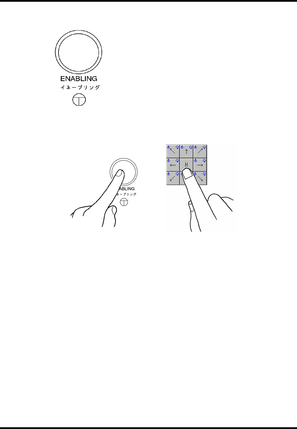
Enabling Switch
To execute jog operation of each NC axis from the control panel during maintenance, operate with one
hand while pressing the enabling switch with the other hand for safety reason.
SW: LW6MB-M1C2MLG (IDEC)
RL131
MAINTENANCE MANUAL
2.3 Maintenance Function
DA8MEC-10-030-A0
2.3-5
2.3.4 Operational Restrictions
Inhibited Operations (Cannot be Stopped Unless Operating Intentionally)
Origin return of all axes
Axis positioning from the Machine adjust - NC MOVE screen
XY axis positioning from the Auto Camera Scale Measurement screen
XY axis positioning from the Board 2 Holes Teaching screen
Z axis positioning by pressing “MOVE WAITING POSITION” on the feeder carriage control panel
Origin return of the rail axis
Positioning of the rail axis from the Machine adjust - Width MOVE screen
Automatic width adjustment from the PCB Data Select screen
Automatic width adjustment from the PCB Data Edit screen
Rail width adjustment from the PCB Data Teaching screen
Any axis operation during production
Permissible Operations (Can be Stopped If Quitting Operation)
Release of safety stop by pressing <START>
Teaching of each axis from the Machine adjust - NC JOG screen (low speed)
Teaching of the XY axis from the Binary Level Setting screen (low speed)
Teaching of the XY axis from the Manual Camera Scale Measurement screen (low speed)
Teaching of the XY axis from the Auto Camera Scale Measurement screen (low speed)
Teaching of the XY axis from the Board 2 Holes screen (low speed)
Teaching of the rail axis from the Machine adjust - Width JOG screen (low speed)
Teaching of the rail axis from the Board Data Teaching screen (low speed)
RL131
MAINTENANCE MANUAL
2.3 Maintenance Function
DA8MEC-10-030-A0
2.3-6
2.3.5 Error Messages
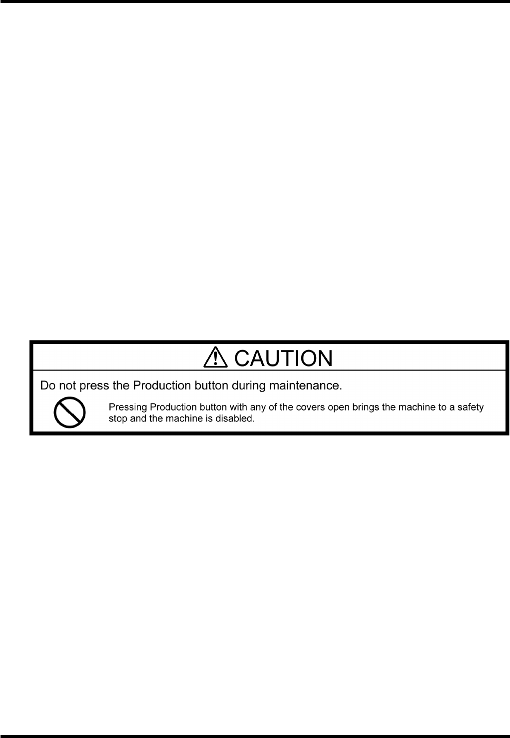
1.
1. When the maintenance switch is turned ON to engage the maintenance mode:
The background of the main menus turns
yellow and the message “During
maintenance” appears to notify the
operator that the maintenance switch is
turned ON and the maintenance mode is
engaged.
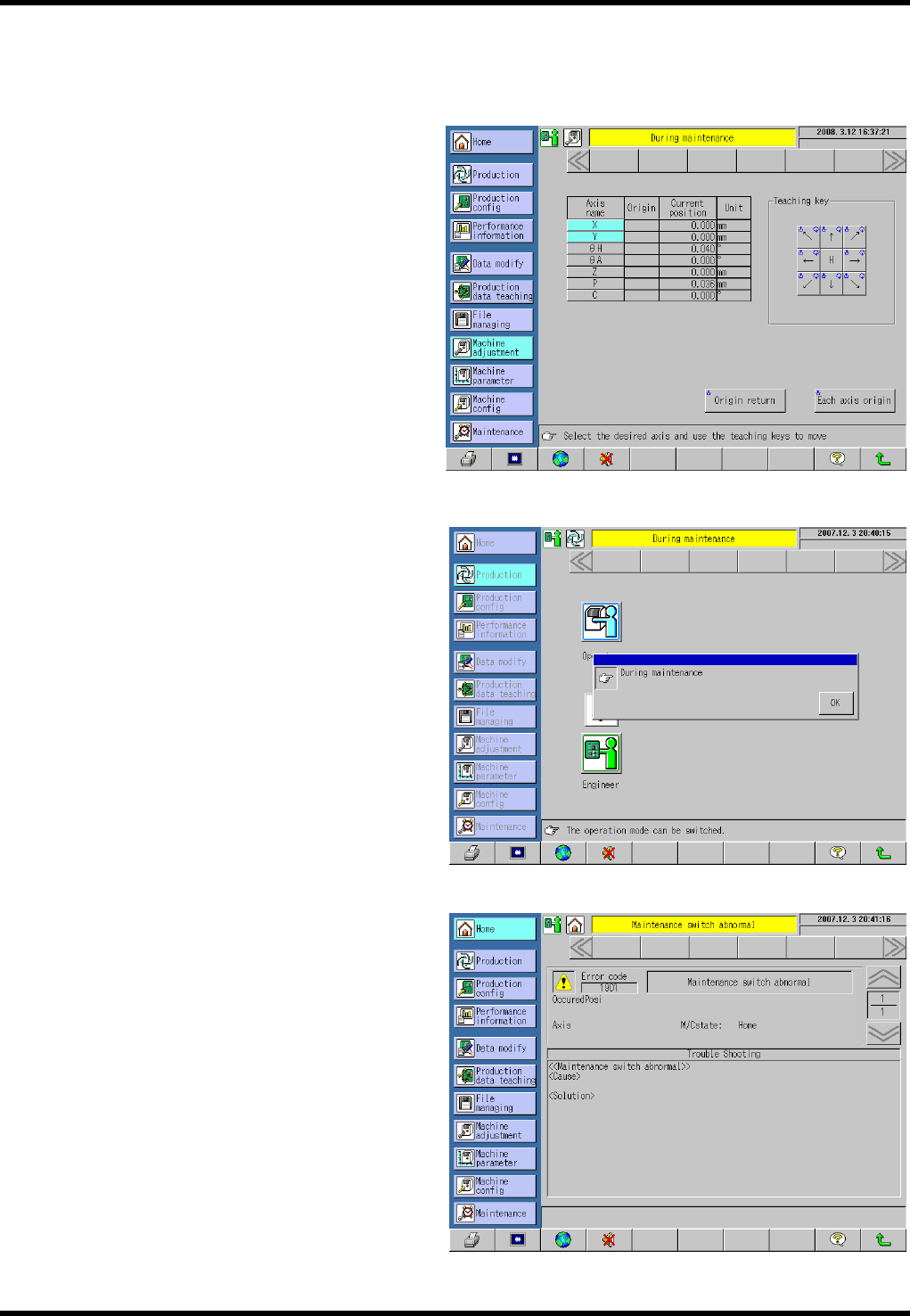
2. When [Production] is pressed in the
maintenance mode:
A pop-up window indicating “During
maintenance” appears. Pressing [OK]
returns the display forcibly to the screen
immediately before [Production] is
pressed.
3. Other
The following error occurs if the
maintenance switch is turned ON after
closing the safety covers, clearing a safety
stop error and closing all covers (all safety
interlock switches are ON and safety stop
error has been cleared (e.g., when the
maintenance switch has been broken)).
Error code: 1901
Error name: Maintenance switch
abnormal
Check the maintenance switch for
detection status.