Maintenance Manual.pdf - 第79页
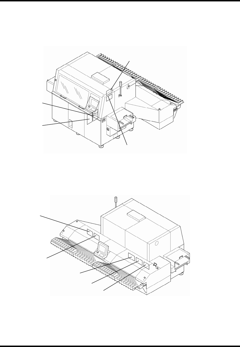
RL131 MAINTENANCE MANUAL 4.1 Control S ystem Configu ration DA8MEC-14-020- A0 4.1-10 4.1.5 Ring I/O Load Board Arrangement K311 K310 K333 K323 K326 K325 K324 K322 K327
RL131
MAINTENANCE MANUAL
4.1 Control System Configuration
DA8MEC-14-020-A0
4.1-9
Function
Error
code No.
Cause Countermeasure
Origin return
error
68
An error occurred during origin
return. Abnormal inhibit input signal
was entered. Parameters required for
origin return have not been set or
invalid values have been set.
Check for abnormality in the switch, limit
sensor, wires and power supply to be
connected to the inhibit inputs (CCWL,
CWL: CN X5 19, 20 pin).
Check the parameters related to the
origin return.
Data
undefined
error
69
Parameters required for the
commanded step or jog movement
have not been set, or invalid values
have been set.
Check the settings of positioning and
step parameters.
Contact our service department.
Current
position
overflow error
70
When the 16.Pr51 (wrap-around
permit) is 0, the current position
(-2147483647 to 2147483647)
overflowed.
Do not send such an operation command
as the current position outside
-2147483647 to 2147483647.
Take particular care for incremental
movement, jog or origin offset.
Drive inhibit
input
detection
error
71
During step or jog movement after
origin return, drive inhibit input for the
moving direction was detected.
Both of the drive inhibit inputs
(CCWL, CWL: CN X5, Pins #19 and
#20) opened.
Check the switches and limit sensors
connected to the drove inhibit input and
wiring or power supply for any problem.
Check the operation command and
installation of the limit sensor.
Check if the direction of origin offset
coincides with that of the drive inhibit
input.
*Max. travel
limit error
72
The command position of the motor
exceeded the maximum travel limit
range in the step or jog mode after
origin return.
Make sure there is no positional
command that exceeds the maximum
travel limit. Take particular care for
incremental movement, jog or origin
offset.
*Motor
automatic
recognition
error
95
The motor and servo amplifier do not
match.
Replace the motor that matches the servo
driver.
Other error
Other
number
may be
shown.
Control circuit malfunctioned due to
excessive noise, etc. The
self-diagnosis function of the servo
driver worked to indicate some kind
of trouble occurred in the servo
amplifier.
Turn power OFF once and turn it back
ON.
If the error persists, the motor and servo
amplifier may be defective.
When this happens, stop the operation
and replace them.
Contact our service department.
=REMARKS=
The protective functions marked with an asterisk (*) below the alarm codes cannot be cleared. Shut
OFF all power sources once and reset the alarm.
RL131
MAINTENANCE MANUAL
4.1 Control System Configuration
DA8MEC-14-020-A0
4.1-10
4.1.5 Ring I/O Load Board Arrangement
K311
K310
K333
K323
K326
K325
K324
K322
K327
RL131
MAINTENANCE MANUAL
4.1 Control System Configuration
DA8MEC-14-020-A0
4.1-11
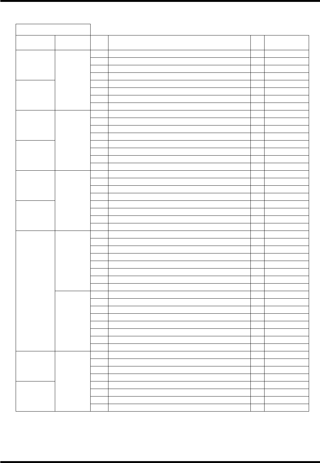
4.1.6 I/O Map
I / O MAP INPUT
Board
connector
Address
No.
Name bit
Note
1
Right rail traverse limit 0
2
Right rail return limit 1
3
PCB detection 1 2
#0_CN16
4
PCB detection 2 3
5
Carry arm return detection 4
6
Carry arm slow down detection 5
7
Carry arm traverse detection 6
#0_CN15
0000
8
7
9
Main frame left side fan alarm 0
10
Main frame controller fan alarm 1
11
Main frame right side fan alarm 2
#0_CN14
12
3
13
4
14
5
15
6
#0_CN13
0001
16
7
17
0
18
1
19
2
#0_CN12
20
3
21
MLP input signal 4
Option
22
Air down 5
23
6
#0_CN11
0002
24
7
25
XY table inside PCB detection 0
26
Positioner error detection 1
27
XY table inside PCB detection 2 2
Option
28
2 PCB transfer 3
Option
29
Positioner lever traverse limit 4
30
Positioner lever return limit 5
31
6
0003
32
7
33
X AXIS+LIMIT 0
34
X AXIS ORG. 1
35
X AXIS-LIMIT 2
36
3
37
Y AXIS+LIMIT 4
38
Y AXIS ORG. 5
39
Y AXIS-LIMIT 6
#0_CN10
0004
40
7
41
Front cover detection 0
42
1
43
Push arm / push up traverse limit 2
Option
#1_CN16
44
Push arm / push up return limit 3
Option
45
Left rail traverse limit 4
46
Left rail return limit 5
47
PCB detection 3 6
#1_CN15
0040
48
PCB detection 4 7