Maintenance Manual.pdf - 第178页
RL131 MAINTENANCE MANUAL 8.1 Insertion Chuck DA8MEC-W 4-400-A0 8.1-1 8.1. Insertion Chuck DA8MEC- W 4-400-A0 8.1.1 A dj usting Ecce ntricity of the In sertion Chuck Unit No. N610052020AA 8.1.1 Adjusting E ccentricity of …

RL131
MAINTENANCE MANUAL
8. MAINTENANCE GUIDE
DA8MEC-83-AA0-A0
8-4

RL131
MAINTENANCE MANUAL
8.1 Insertion Chuck
DA8MEC-W4-400-A0
8.1-1
8.1. Insertion Chuck
DA8MEC-W4-400-A0
8.1.1 Adjusting Eccentricity of the Insertion Chuck
Unit No. N610052020AA
8.1.1 Adjusting Eccentricity of the
Insertion Chuck
8.1.2 Adjusting Height of the
Insertion Chuck
Adjusting Eccentricity
1.
1. Turn the power ON to return the machine to its origin.
2. Open the front cover.
3. Loosen the fitting bolt of the head cover and detach the
head cover from the head.
4. Turn ON the maintenance switch.
5. Press <ENABLING> + <START> to clear the error.
6. Rotate the handwheel to set the cycle timer to 0°.
7. Set an electronic component jig upside down.
Jig No.: X01A08006
8. Press [Machine Adjustment] [qH axis servo free].
9. Turn the belt of the insertion head manually to check the
eccentricity.
If decentered, proceed to the following steps.
10. Free the M3 bolt (1).
11. Free the lock screw at the back of the fine
adjustment screw (A).
12. Adjust the eccentricity in the vertical direction by
rotating the fine adjustment screw (A).
13. Free the set screw (1).
14. Adjust the eccentricity in the vertical direction by
rotating the fine adjustment screw (B).
=REMARKS=
Make eccentricity check visually or by using
the dial gauge’s probe set on the
component jig that has been set upside
down in the chuck.
The fine adjustment screws move in the
vertical direction with respect to the unit. However, check the initial mounting plane and condition
before loosening them. They may shift toward other direction.
15. Retighten the fitting bolt of the head cover to reattach the head cover.
16. Turn OFF the maintenance switch.
Handwheel
Normal catching Reverse catching
Electronic
component jig
Rotate the head by hand
to check for eccentricity
Setting electronic component jig
Fine adjustment
screw (A)
Lock screw
Set screw
Fine adjustment
screw (B)
M3 bolt
RL131
MAINTENANCE MANUAL
8.1 Insertion Chuck
DA8MEC-W4-400-A0
8.1-2
8.1.2 Adjusting Height of the Insertion Chuck
Unit No. N610074520AA
8.1.1 Adjusting Eccentricity of the
Insertion Chuck
8.1.2 Adjusting Height of the
Insertion Chuck
8.1.3 Adjusting Open/Close Timing
of the Insertion Chuck Claw
Adjusting height
2.
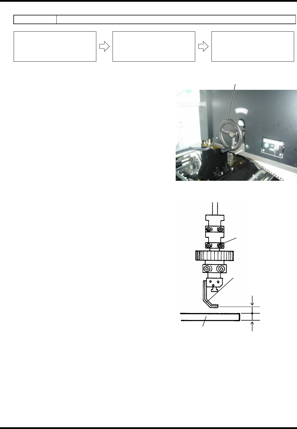
1. Set a PC board to the X-Y table. (t=1.6 mm)
2. Rotate the handwheel to set the cycle timer to 145°.
(Bottom dead center of the insertion chuck)
3. Check that the clearance between the chuck claw and
PC board is 0.9 mm.
If not, proceed to the steps below.
4. Loosen the bolt (A) and adjust the chuck claw by moving
up/down.
5. Rotate the handwheel by one turn again to set the cycle
timer to 145°. (Bottom dead center of the insertion
chuck)
6. If the clearance between the chuck claw and PC board is
0.9 mm, adjustment is completed.
=REMARKS=
If the clearance is not 0.9 mm, repeat steps 4 to 6
again.
Handwheel
Bolt (A)
Chuck claw
PC board
0.9 mm
1.6 mm