Maintenance Manual.pdf - 第55页
RL1 31 MAINTENANCE MANUAL 3.1 O utline of I nstall ation DA8ME C-11-010- A0 3.1- 2 3.1. 3 T ransport Tr ansport of the m achine is carried out by our ser v i ce personnel . = R E M A R K S = If the customer should mov e …

RL131
MAINTENANCE MANUAL
3.1 Outline of Installation
DA8MEC-11-010-A0
3.1-1
3.1. Outline of Installation
DA8MEC-11-010-A0
Basically, installation is carried out by our service personnel.
This chapter describes fundamental installation works.
3.1.1 Environmental Requirements
If the machine has not been installed properly, expected functions cannot be attained.
Install the machine in a location where the following conditions can be met:
Adequate electric capacity to the machine
The power supply voltage fluctuation shall be within ±10V for 200/220V AC or within ±20V for
380/400/420/480V AC.
Grounding work with Class D (Class 3) or upper grade.
Supply air of 0.5 MPa and adequate rate must be assured.
Room temperature in the range of 10 to 30°C.
Humidity in the range of 25 (0°C) to 75% (40°C) with no condensation.
Height above sea level: 1,000 m or below.
Storage temperature in the range of -20 to 60°C.
Storage humidity of 75% (60°C) or less (relative humidity), 0.029 kg/kg or less (absolute humidity).
Capable of sustaining the mass of the machine.
No considerable vibration.
No inflammable or corrosive gas.
No dust and/or soot.
=REMARKS=
This machine complies with the essential health and safety requirements in accordance with the
industrial provisions of EC Council Directives. Accordingly, the electrical components, cables and
devices must be our recommended maintenance-parts.
Our customers should not remodel machine by another maintenance-parts all by oneself.
3.1.2 Disturbance of TV Monitor due to Electromagnetic Noise
If this machine is exposed to strong radial field or strong magnetic field, TV monitor may be disturbed. But
this does not cause functional loss.
RL131
MAINTENANCE MANUAL
3.1 Outline of Installation
DA8MEC-11-010-A0
3.1-2
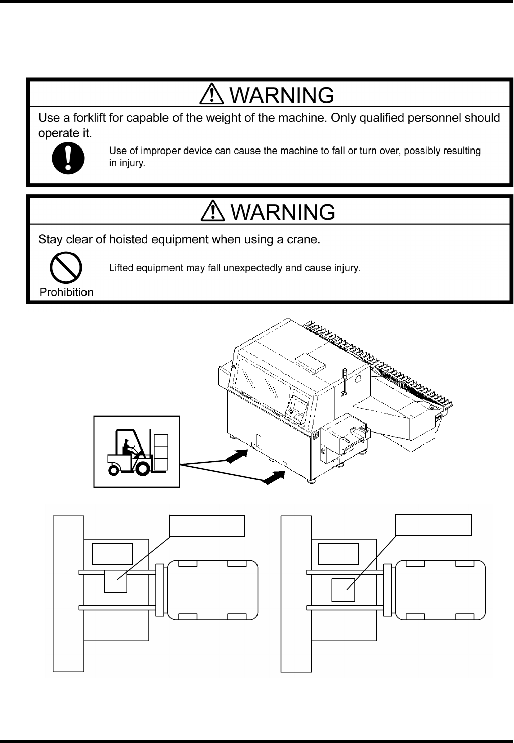
3.1.3 Transport
Transport of the machine is carried out by our service personnel.
=REMARKS=
If the customer should move the machine by himself, use an adequate apparatus capable of the weight
of the machine.
=REMARKS=
Do not insert the forks of the forklift or other lifting equipment into the center part (lower anvil) of the
machine.
Part
supply
unit
RL131
Forklift
Lower anvil
NG
Part
supply
unit
RL131
Forklift
Lower anvil
OK
Folklift insertion position
RL131
MAINTENANCE MANUAL
3.1 Outline of Installation
DA8MEC-11-010-A0
3.1-3
3.1.4 Installation
Install the machine even with the ground by using a spirit level.
=REMARKS=
If the machine has not been installed level with the ground, the expected functions cannot be attained.
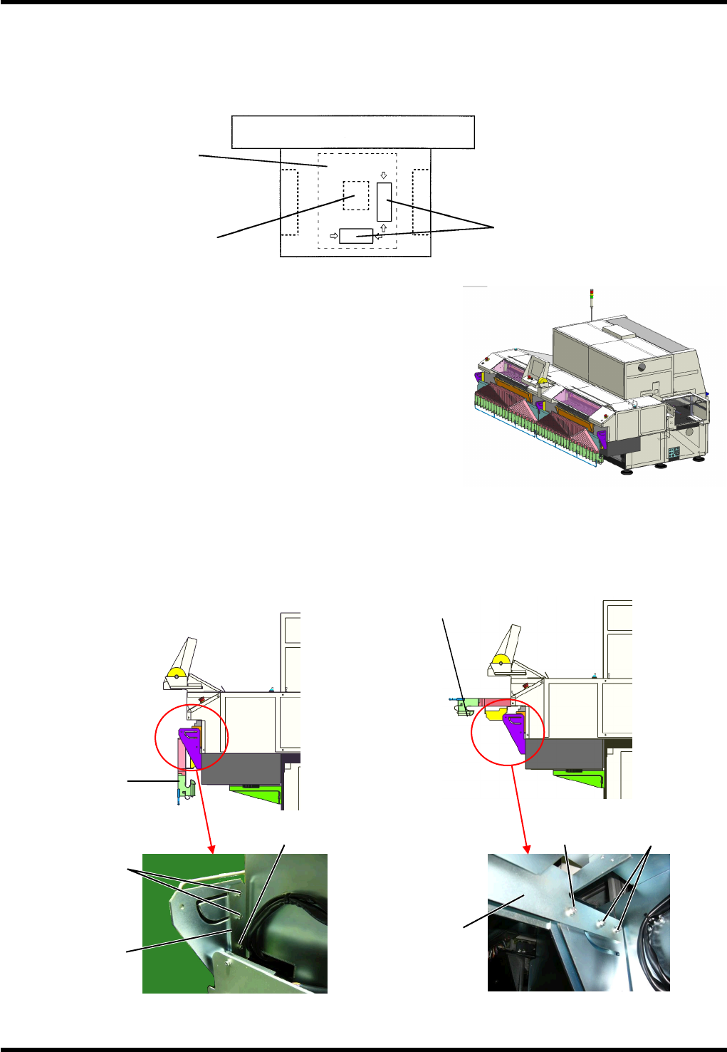
Setting guide plate
During transport, the guide plate of the machine is oriented in
vertical position as shown in Figure 1.
When installing the machine, take the following steps to change
its orientation to horizontal position (Figure 3):
1.
1. Remove the bolt 1 securing the bracket on the side of the
guide plate.
2. Loosen the bolt 2 securing the bracket on the side of the
guide plate.
3. Hold the guide plate guide and raise the top panel from the
position in Figure 2 to the one in Figure 3.
4. Reattach the bolt 1 to the bracket on the side of the guide
plate.
5. Secure the bolts 1 and 2 at the position where the guide plate is almost parallel with the installation floor.
(Tightening torque: 10N·m)
Figure 3
Bolt 1 Bolt 2
Guide plate
Guide plate
Figure 2
Bolt 2
Bolt 1
Guide plate
Guide plate
Part supply unit
Places where the spirit
level takes a seat
Loader
Unloader
Anvil unit
XY table base
Figure 1