Maintenance Manual.pdf - 第78页
RL131 MAINTENANCE MANUAL 4.1 Control S ystem Conf iguration DA8MEC-14-020- A0 4.1-9 Function Error code No. Cause Count ermeasure Origin return error 68 An error occ urred during ori gin return. Abnorm al inhibit inp ut …

RL131
MAINTENANCE MANUAL
4.1 Control System Configuration
DA8MEC-14-020-A0
4.1-8
Function
Error
code No.
Cause Countermeasure
*Encoder
communi-
cation error
21
Communication between the encoder
and servo amplifier was interrupted
at a certain count and breaking
detection function activated.
Encoder
communi-
cation data
error
23
Data from the encoder caused
communication error. (Mainly due to
noise in the data) Although the data
was received successfully, the
contents of data were abnormal.
Connect the encoder cable according to
the wiring diagram.
Reconnect the connector pins correctly.
Connect the encoder cable to the CN X6
connector. (Check if the connector is not
connected to the CNX7 connector for the
external scale.)
Secure the power supply voltage 5V
DC±5% (4.75 to 5.25V) of the encoder.
Use care especially when the encoder
cable is long.
Separate the motor cable from the
encoder cable if connected together.
Excessive
positional
deviation
24
Positional deviation pulse exceeded
the set value.
1. The motor failed to follow the
movement of command.
1. Check if the motor rotates according to
the position command.
Check the torque monitor for saturated
output torque. Adjust the gain. Set
SV.Pr5E (1st torque limit setting) to the
maximum value. Connect the encoder
according to the wiring diagram. Increase
the acceleration/ deceleration time and
lighten the load to decrease the speed.
Overspeed 26
Motor rotating speed exceeded the
set value .
Check for any excessive speed
command issued.
Deviation
counter
overflow
29
Deviation counter exceeded 2
27
(134217728).
Contact our service department.
Software limit
34
The motor exceeded the allowable
movable range set by the SV.Pr26
(Software limit setting) for the
position command input range.
1. The gain is not matched.
1. Contact our service department.
*EEPROM
parameter
error
36
When reading the data from the
EEPROM at power ON, the
parameter save area data was found
to be destroyed.
Set all parameters again.
If the error persists, the EEPROM may
be defective. Replace the servo amplifier.
Contact our service department.
*EEPROM
check code
error
37
When reading the data from the
EEPROM at power ON, the
EEPROM write check data was
found to be destroyed.
Replace the servo driver because it may
be faulty.
Contact our service department.
Emergency
stop input
error
39
When the emergency stop input
(EMG-STP: CN X5 2 pin) is turned
OFF, the system takes it as an error
and trip occurs.
Check for any abnormality in the switch
power or wires connected to the
emergency stop input.
Check that the emergency stop input (CN
X5 2 pin) is turned ON.
Check that the rising time of the control
signal wire (12 to 24V DC) at power ON
is not longer than the one for the servo
driver.
*Encoder Z
phase error
48
Missing pulses of serial encoder
Z-phase were detected. (2500 [p/r]
5).
Replace the servomotor.
*Encoder CS
signal error
49
CS signal logic error of serial
encoder was detected. (2500 [p/r] 5)
Encoder is at fault.
Replace the servomotor.
RL131
MAINTENANCE MANUAL
4.1 Control System Configuration
DA8MEC-14-020-A0
4.1-9
Function
Error
code No.
Cause Countermeasure
Origin return
error
68
An error occurred during origin
return. Abnormal inhibit input signal
was entered. Parameters required for
origin return have not been set or
invalid values have been set.
Check for abnormality in the switch, limit
sensor, wires and power supply to be
connected to the inhibit inputs (CCWL,
CWL: CN X5 19, 20 pin).
Check the parameters related to the
origin return.
Data
undefined
error
69
Parameters required for the
commanded step or jog movement
have not been set, or invalid values
have been set.
Check the settings of positioning and
step parameters.
Contact our service department.
Current
position
overflow error
70
When the 16.Pr51 (wrap-around
permit) is 0, the current position
(-2147483647 to 2147483647)
overflowed.
Do not send such an operation command
as the current position outside
-2147483647 to 2147483647.
Take particular care for incremental
movement, jog or origin offset.
Drive inhibit
input
detection
error
71
During step or jog movement after
origin return, drive inhibit input for the
moving direction was detected.
Both of the drive inhibit inputs
(CCWL, CWL: CN X5, Pins #19 and
#20) opened.
Check the switches and limit sensors
connected to the drove inhibit input and
wiring or power supply for any problem.
Check the operation command and
installation of the limit sensor.
Check if the direction of origin offset
coincides with that of the drive inhibit
input.
*Max. travel
limit error
72
The command position of the motor
exceeded the maximum travel limit
range in the step or jog mode after
origin return.
Make sure there is no positional
command that exceeds the maximum
travel limit. Take particular care for
incremental movement, jog or origin
offset.
*Motor
automatic
recognition
error
95
The motor and servo amplifier do not
match.
Replace the motor that matches the servo
driver.
Other error
Other
number
may be
shown.
Control circuit malfunctioned due to
excessive noise, etc. The
self-diagnosis function of the servo
driver worked to indicate some kind
of trouble occurred in the servo
amplifier.
Turn power OFF once and turn it back
ON.
If the error persists, the motor and servo
amplifier may be defective.
When this happens, stop the operation
and replace them.
Contact our service department.
=REMARKS=
The protective functions marked with an asterisk (*) below the alarm codes cannot be cleared. Shut
OFF all power sources once and reset the alarm.
RL131
MAINTENANCE MANUAL
4.1 Control System Configuration
DA8MEC-14-020-A0
4.1-10
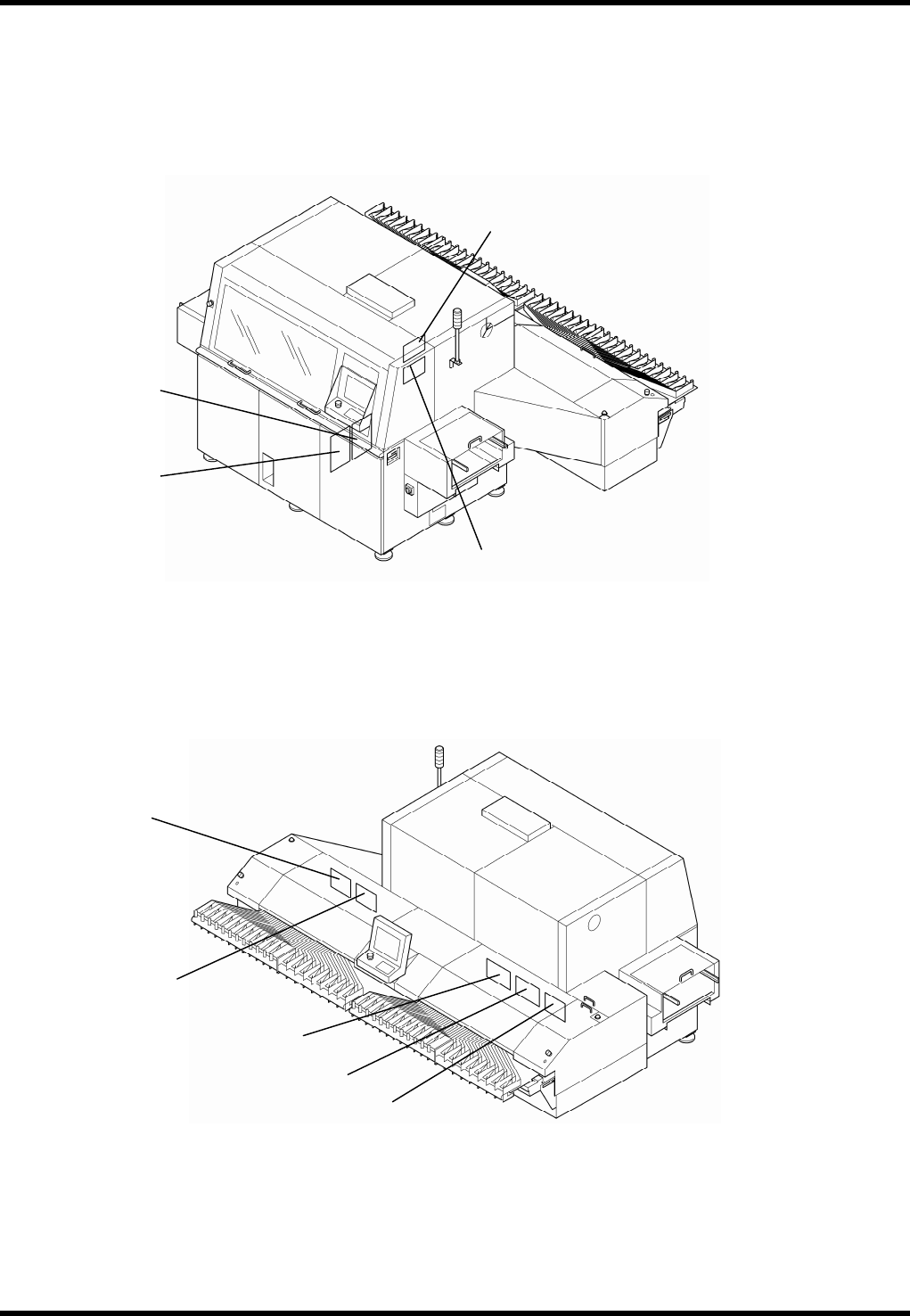
4.1.5 Ring I/O Load Board Arrangement
K311
K310
K333
K323
K326
K325
K324
K322
K327