Maintenance Manual.pdf - 第89页
RL131 MAINTENANCE MANUAL 4.1 Control S ystem Configu ration DA8MEC-14-020- A0 4.1-20 I / O M AP INPUT Board connector Address No. Name bit Note #22_CNMC2 441 Therm al 1 (Vacuum pum p) 0 #22_CNMC3 442 1 #22_CNMC4 443 2 #2…
RL131
MAINTENANCE MANUAL
4.1 Control System Configuration
DA8MEC-14-020-A0
4.1-19
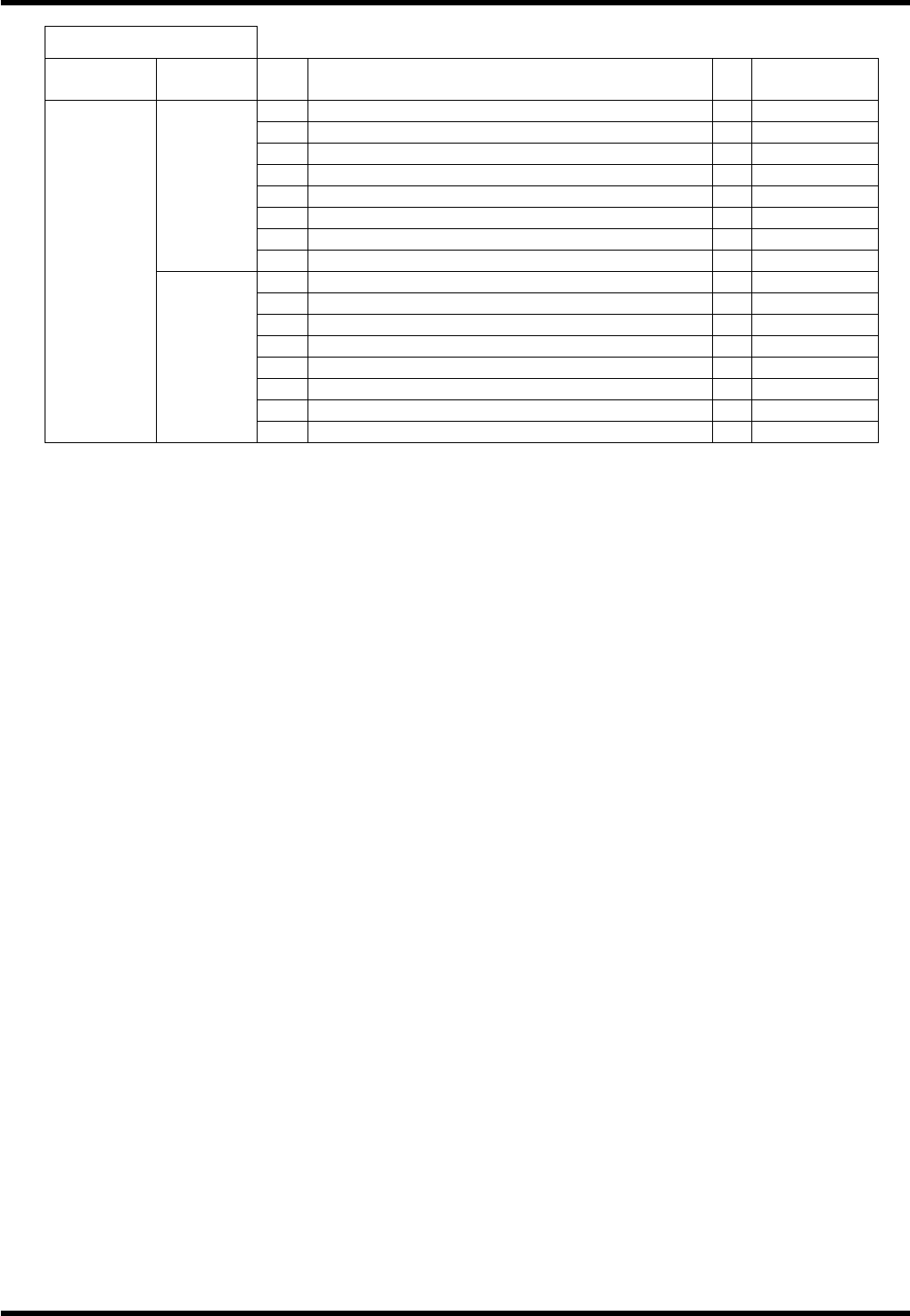
I / O MAP INPUT
Board
connector
Address
No.
Name bit
Note
417
End detection 65 0
418
End detection 66 1
419
End detection 67 2
420
End detection 68 3
421
End detection 69 4
422
End detection 70 5
423
End detection 71 6
0443
424
End detection 72 7
425
End detection 73 0
426
End detection 74 1
427
End detection 75 2
428
End detection 76 3
429
End detection 77 4
430
End detection 78 5
431
End detection 79 6
#17_CN10
0444
432
End detection 80 7
RL131
MAINTENANCE MANUAL
4.1 Control System Configuration
DA8MEC-14-020-A0
4.1-20
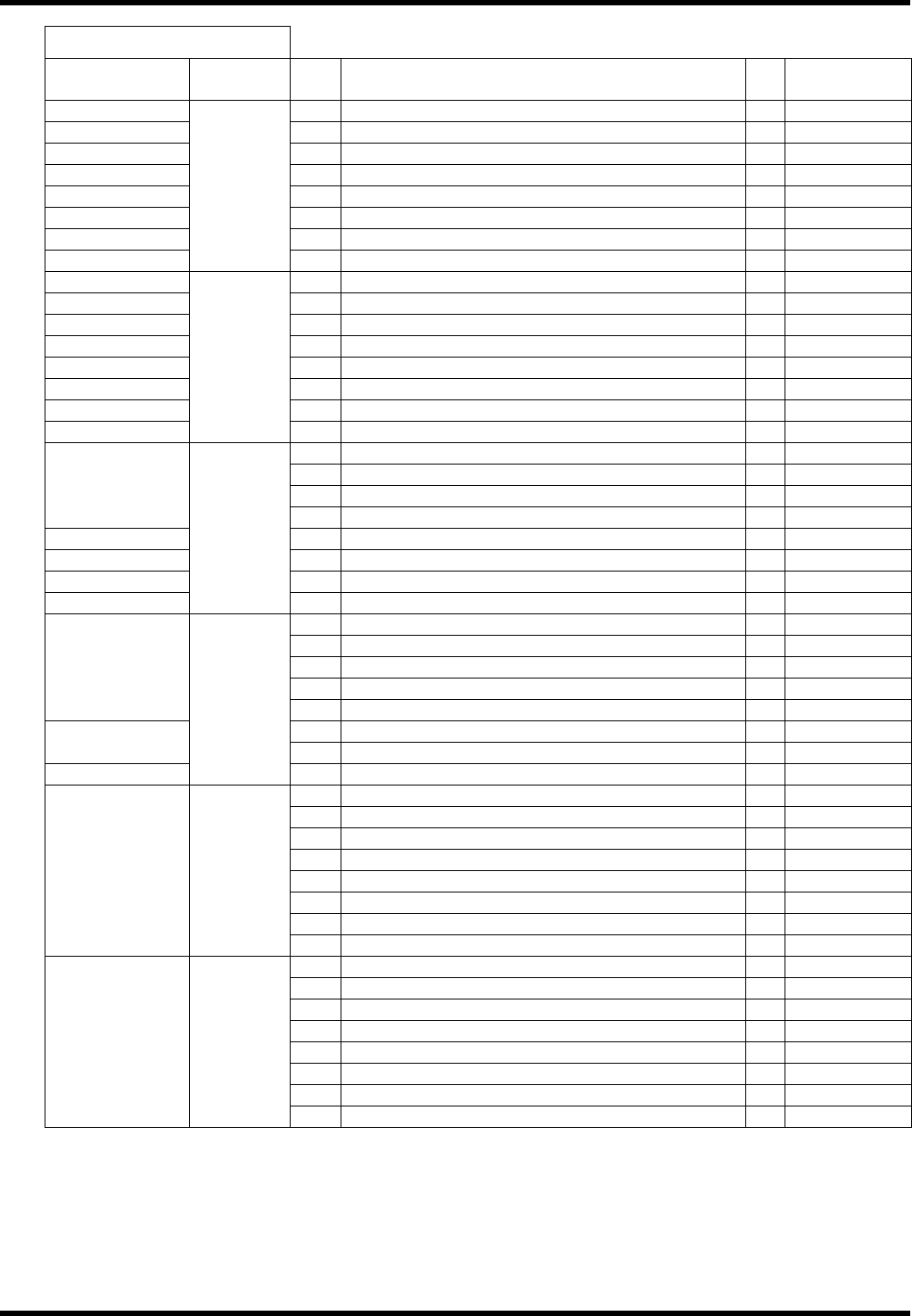
I / O MAP INPUT
Board
connector
Address
No.
Name bit
Note
#22_CNMC2 441
Thermal 1 (Vacuum pump) 0
#22_CNMC3 442
1
#22_CNMC4 443
2
#22_CNMC5 444
3
#22_CNMST 445
Maintenance switch detection 4
#22_Inside 446
Safety relay status (closed) 5
#22_Inside 447
Motor 24V power status (closed) 6
#22_Inside
0580
448
Instantaneous stop detection status 7
#22_CNCONV1
449
Front right cover detection 0
#22_CNCONV2
450
Front left cover detection 1
#22_CNCONV3
451
Part supply unit R cover detection 2
#22_CNCONV4
452
Part supply unit L cover detection 3
#22_CNEMG1 453
Front right emergency stop SW detection 4
#22_CNEMG2 454
Front left emergency stop SW detection 5
#22_CNEMG3 455
Rear right emergency stop SW detection 6
#22_CNEMG4
0581
456
Rear left emergency stop SW detection 7
457
Servo ON signal 0
458
Maintenance switch input 1
459
System reserve 2
#22_CNXIN
460
Servo free 3
#22_CNLM1 461
Y axis plus minus overrun detection 4
#22_CNLM2 462
X axis plus minus overrun detection 5
#22_CNLM3 463
6
#22_CNLM4
0582
464
7
465
0
466
1
467
2
468
3
#22_ −
469
4
470
Preceding process production end (FEND) 5
#22_CN00
471
Loader stocker ready signal 6
#22_CN01
0583
472
Unloader stocker ready signal 7
1
Right rail forward valve 0
2
Right rail reverse valve 1
3
Right belt motor right turn 2
4
Right belt motor reverse turn 3
5
Safety stop support valve 4
6
5
7
6
#0_CN5 0020
8
7
9
0
10
1
11
Recognition light source ON 2
12
Recognition light source ON 3
13
Recognition light source ON 4
14
5
15
6
#0_CN7 0021
16
7
RL131
MAINTENANCE MANUAL
4.1 Control System Configuration
DA8MEC-14-020-A0
4.1-21
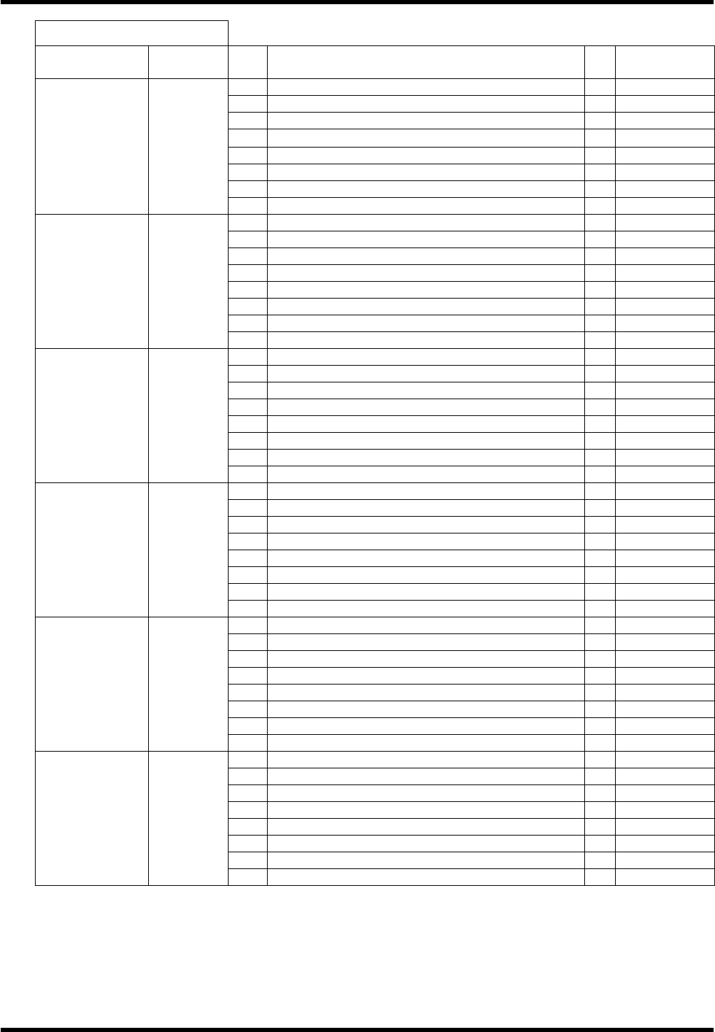
I / O MAP OUTPUT
Board
connector
Address
No.
Name bit
Note
17
Right reference valve 0
Option
18
Reference pin valve 1
Option
19
2
20
3
21
PCB supply valve 4
Option
22
PCB stopper 1 valve 5
Option
23
6
#0_CN9 0022
24
7
25
ZR axis parts changing lamp output 0
26
ZR axis parts changing signal 1
27
ZL axis parts changing lamp output 2
28
ZL axis parts changing signal 3
29
4
30
5
31
6
#0_CN6 0023
32
7
33
Left rail forward valve 0
34
Left rail reverse valve 1
35
Left belt motor right turn 2
36
Left belt motor reverse turn 3
37
Positioner lever valve 4
38
5
39
6
#1_CN5 0060
40
7
41
0
42
Inverter reverse signal 1
43
Inverter speed command 1 2
44
Inverter speed command 2 3
45
Inverter abnormal reset 4
46
Transfer brake release 5
47
Inverter speed command 3 6
#1_CN7 0061
48
7
49
Insertion detection signal output 1 0
50
Insertion detection signal output 2 1
51
Insertion detection signal output 3 2
52
3
53
Insertion detection signal output 4 4
54
Insertion detection signal output 5 5
55
Insertion detection signal output 6 6
#1_CN9 0062
56
7
57
Guide pin select 1 0
58
Guide pin select 2 (2.5) 1
59
Guide pin select 3 (5.0) 2
60
3
61
4
62
5
63
6
#1_CN6 0063
64
7