Maintenance Manual.pdf - 第81页
RL131 MAINTENANCE MANUAL 4.1 Control S ystem Configu ration DA8MEC-14-020- A0 4.1-12 I / O M AP INPUT Board connector Address No. Name bit Note 49 0 50 1 51 2 #1_CN14 52 3 53 q A AXIS+LIMIT 4 54 q A AXIS ORG. 5 55 q A AX…
RL131
MAINTENANCE MANUAL
4.1 Control System Configuration
DA8MEC-14-020-A0
4.1-11
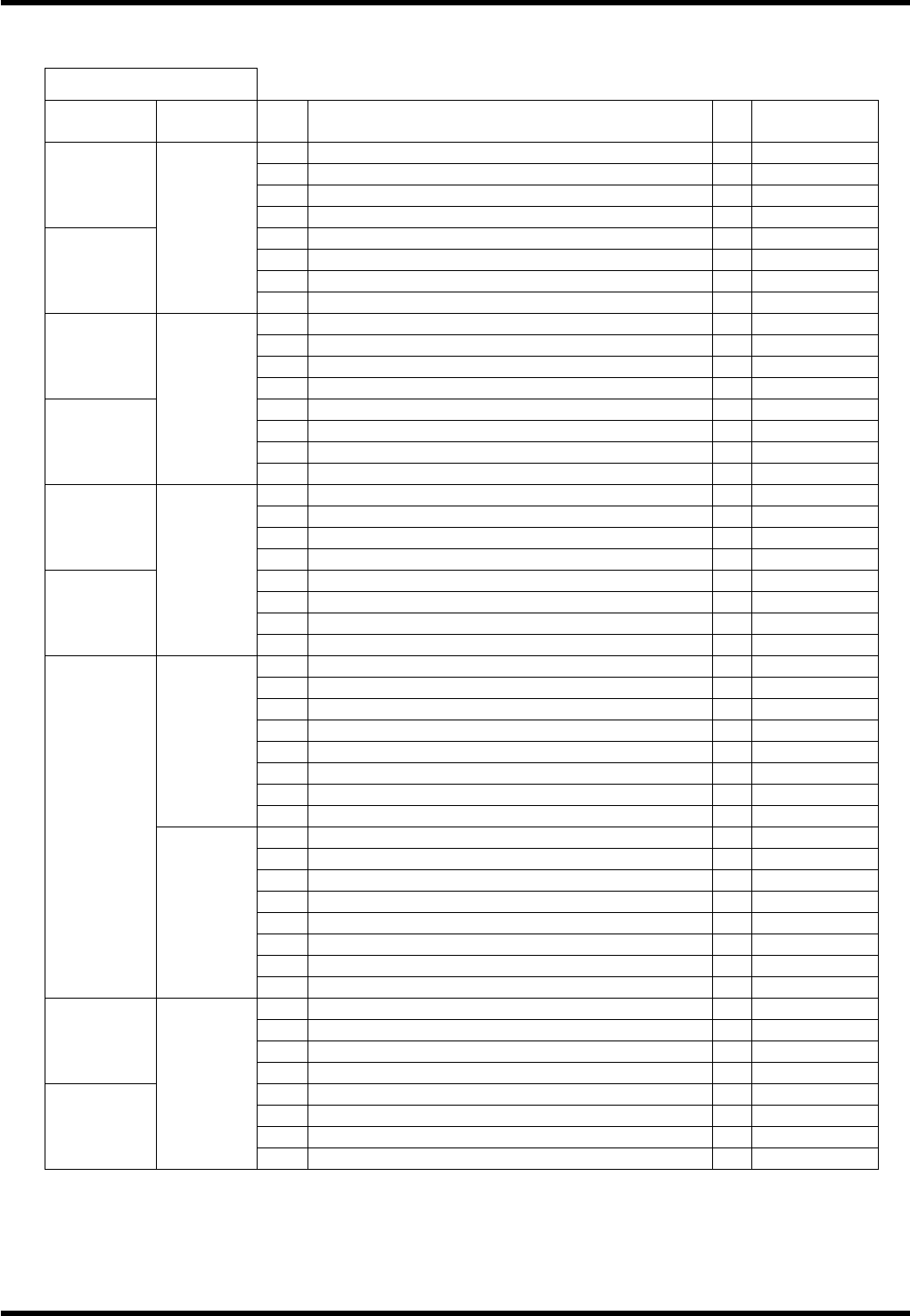
4.1.6 I/O Map
I / O MAP INPUT
Board
connector
Address
No.
Name bit
Note
1
Right rail traverse limit 0
2
Right rail return limit 1
3
PCB detection 1 2
#0_CN16
4
PCB detection 2 3
5
Carry arm return detection 4
6
Carry arm slow down detection 5
7
Carry arm traverse detection 6
#0_CN15
0000
8
7
9
Main frame left side fan alarm 0
10
Main frame controller fan alarm 1
11
Main frame right side fan alarm 2
#0_CN14
12
3
13
4
14
5
15
6
#0_CN13
0001
16
7
17
0
18
1
19
2
#0_CN12
20
3
21
MLP input signal 4
Option
22
Air down 5
23
6
#0_CN11
0002
24
7
25
XY table inside PCB detection 0
26
Positioner error detection 1
27
XY table inside PCB detection 2 2
Option
28
2 PCB transfer 3
Option
29
Positioner lever traverse limit 4
30
Positioner lever return limit 5
31
6
0003
32
7
33
X AXIS+LIMIT 0
34
X AXIS ORG. 1
35
X AXIS-LIMIT 2
36
3
37
Y AXIS+LIMIT 4
38
Y AXIS ORG. 5
39
Y AXIS-LIMIT 6
#0_CN10
0004
40
7
41
Front cover detection 0
42
1
43
Push arm / push up traverse limit 2
Option
#1_CN16
44
Push arm / push up return limit 3
Option
45
Left rail traverse limit 4
46
Left rail return limit 5
47
PCB detection 3 6
#1_CN15
0040
48
PCB detection 4 7
RL131
MAINTENANCE MANUAL
4.1 Control System Configuration
DA8MEC-14-020-A0
4.1-12
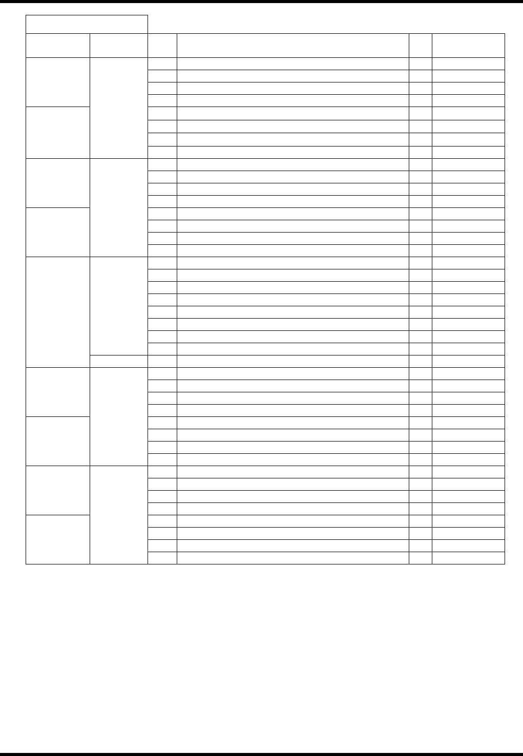
I / O MAP INPUT
Board
connector
Address
No.
Name bit
Note
49
0
50
1
51
2
#1_CN14
52
3
53
qA AXIS+LIMIT
4
54
qA AXIS ORG.
5
55
qA AXIS-LIMIT
6
#1_CN13
0041
56
7
57
Insertion check 1 0
58
Insertion check 2 1
59
Insertion check 3 2
#1_CN12
60
Insertion check 4 3
61
4
62
5
63
Invertor run signal 6
#1_CN11
0042
64
Invertor abnormal signal 7
65
ZR change SW 0
66
1
67
2
68
3
69
4
70
5
71
6
0043
72
7
#1_CN10
0044 73
0
161
0
162
1
163
2
#4_CN14
164
3
165
CVT check 1 4
Option
166
CVT check 2 5
Option
167
6
#4_CN13
0101
168
7
169
PCB request delay 0
Option
170
PCB supply delay 1
Option
171
2
#4_CN12
172
3
173
4
174
5
175
6
#4_CN11
0102
176
7
RL131
MAINTENANCE MANUAL
4.1 Control System Configuration
DA8MEC-14-020-A0
4.1-13
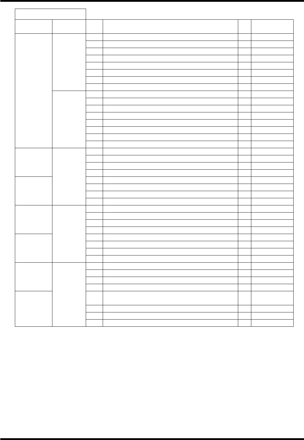
I / O MAP INPUT
Board
connector
Address
No.
Name bit
Note
177
Vacuum upper limit (BSF-V) 0
Option
178
Vacuum lower limit (BSF-V) 1
Option
179
PCB vacuum detection (BSF-V) 2
Option
180
PCB carry traverse limit (BSF-V) 3
Option
181
PCB carry return limit (BSF-V) 4
Option
182
No-PCB detection (BSF-V) 5
Option
183
Safety cover SW (BSF-V) 6
Option
0103
184
VACUUM SW (BSF-V) 7
Option
185
UP SW (BSF-V) 0
Option
186
DOWN SW (BSF-V) 1
Option
187
Rail open/close SW (BSF-V) 2
Option
188
FOWARD SW (BSF-V) 3
Option
189
REVERSE SW (BSF-V) 4
Option
190
5
191
6
#4_CN10
0104
192
7
193
L shutter lower left limit 0
194
L shutter lower right limit 1
195
L shutter upper left limit 2
#12_CN16
196
L shutter upper right limit 3
197
R shutter lower left limit 4
198
R shutter lower right limit 5
199
R shutter upper left limit 6
#12_CN15
0300
200
R shutter upper right limit 7
201
V cutter return detection 0
202
Tape detection after V-cut 1
203
Pallet chuck lock close detection 2
#12_CN14
204
3
205
Pallet part position check 1 4
206
Pallet part position check 2 5
207
Pallet part detection 6
#12_CN13
0301
208
Pallet part remain detection 7
209
C AXIS ORG 0
210
1
211
2
#12_CN12
212
3
213
Cover open/close safety SW (Part processing
unit)
4
214
Cover open/close safety SW (Pulley) 5
215
6
#12_CN11
0302
216
7