Maintenance Manual.pdf - 第71页
RL131 MAINTENANCE MANUAL 4.1 Control S ystem Configu ration DA8MEC-14-020- A0 4.1-2 4.1.2 Control Unit Arrangement Front Rear Maintenance s witch Emergenc y stop switch AC servo m otor driver Pulse m otor driver (Opt…
RL131
MAINTENANCE MANUAL
4.1 Control System Configuration
DA8MEC-14-020-A0
4.1-1
4.1. Control System Configuration
DA8MEC-14-020-A0
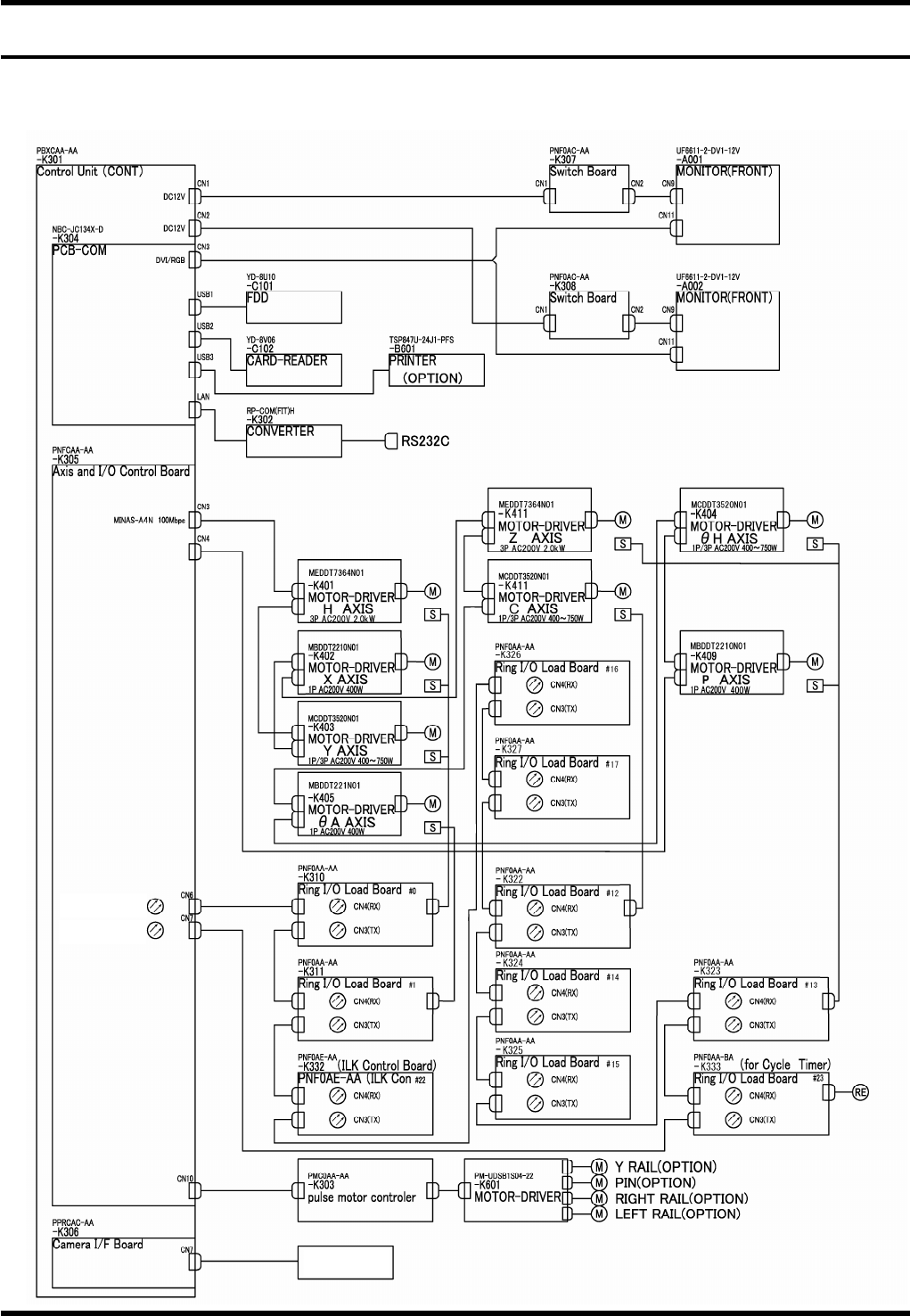
4.1.1 Block Diagram
Hole recognition
camera
Transmission for
ring I/O
Transmission for
ring I/O
RL131
MAINTENANCE MANUAL
4.1 Control System Configuration
DA8MEC-14-020-A0
4.1-2
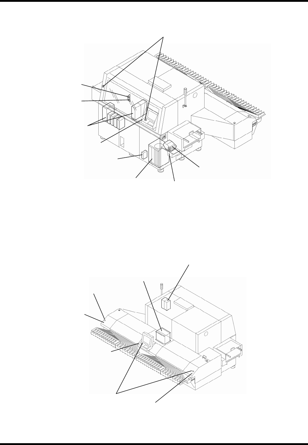
4.1.2 Control Unit Arrangement
Front
Rear
Maintenance switch
Emergency stop switch
AC servo motor driver
Pulse motor driver
(Option for automatic width
adjustment)
Enabling switch
Printer
Main switch
Main controller
Enabling switch
Emergency stop switch
Transformer box
AC servo motor driver
Enabling switch
Emergency stop switch
Parts exchange switch
Parts exchange switch
RL131
MAINTENANCE MANUAL
4.1 Control System Configuration
DA8MEC-14-020-A0
4.1-3
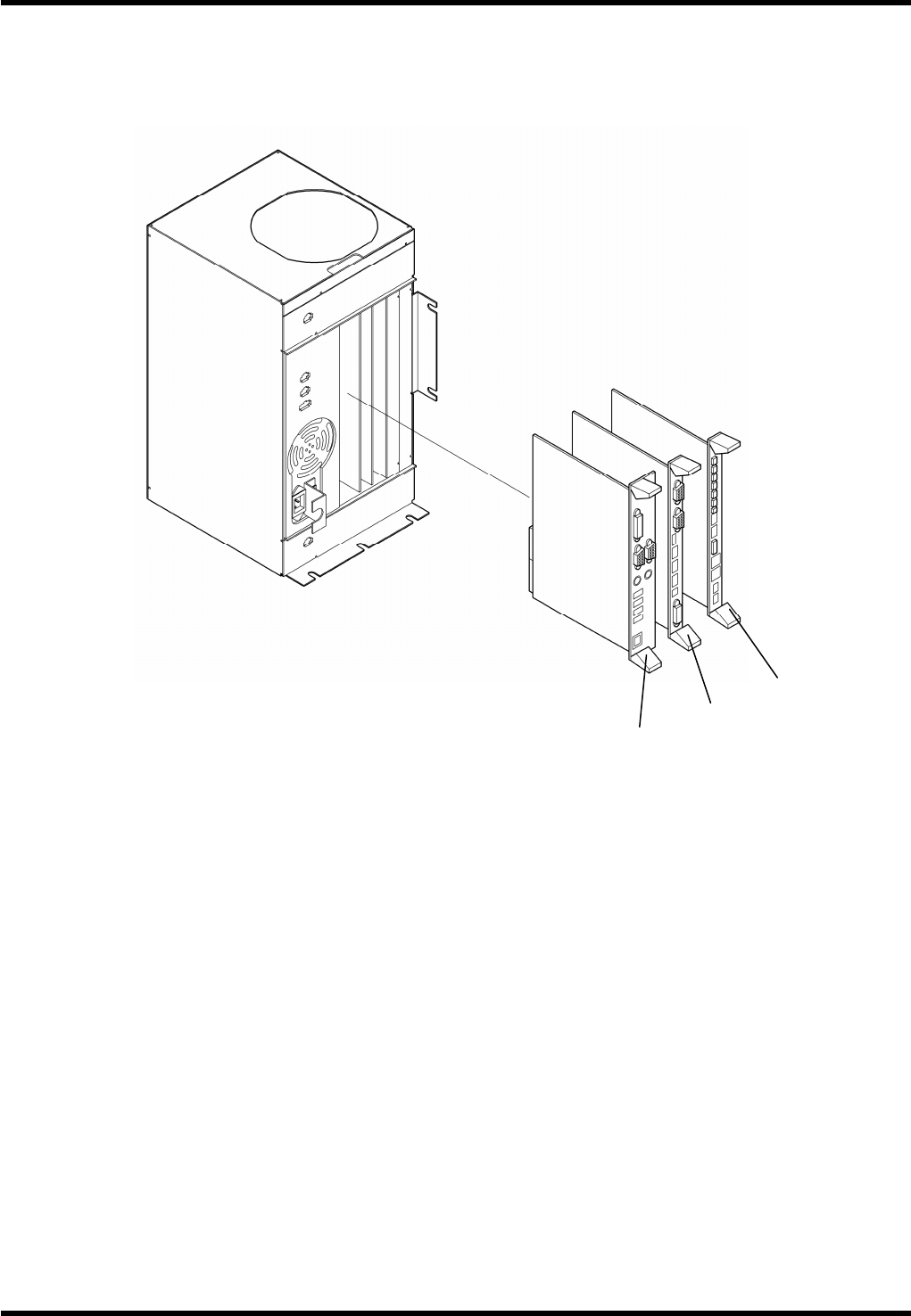
4.1.3 P9
General Description
P9 is a single CPU system controller featuring a 32-bit microcomputer.
Board Configuration
P9 consists of the following boards:
1.
1. PCB-COM board
Model: NBC-JC134X-D
Function: PCB-COM board interfaces with exterior devices.
2. Camera interface board
Model: PPRCAC-AA
Function: The component insertion hole data from the CCD camera is written into the memory and
calculated in comparison to the previously determined standard hole position.
3. Axis and I/O control board
Model: PNFCAA-AA
Function: The board sends signals to AC servo drivers according to values set in the NC program in
order to control AC servomotors.
1.
2.
3.