Maintenance Manual.pdf - 第56页
RL1 31 MAINTENANCE MANUAL 3.1 O utline of I nstall ation DA8ME C-11-010- A0 3.1- 3 3.1. 4 Install at ion Instal l t he machine ev en with the ground by using a spiri t lev el. = R E M A R K S = If the machine has not bee…
RL131
MAINTENANCE MANUAL
3.1 Outline of Installation
DA8MEC-11-010-A0
3.1-2
3.1.3 Transport
Transport of the machine is carried out by our service personnel.
=REMARKS=
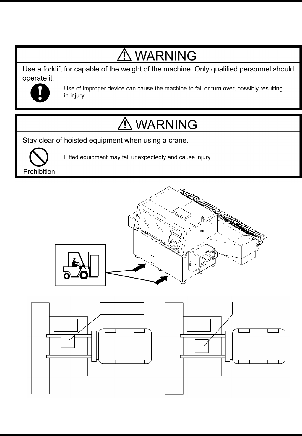
If the customer should move the machine by himself, use an adequate apparatus capable of the weight
of the machine.
=REMARKS=
Do not insert the forks of the forklift or other lifting equipment into the center part (lower anvil) of the
machine.
Part
supply
unit
RL131
Forklift
Lower anvil
NG
Part
supply
unit
RL131
Forklift
Lower anvil
OK
Folklift insertion position
RL131
MAINTENANCE MANUAL
3.1 Outline of Installation
DA8MEC-11-010-A0
3.1-3
3.1.4 Installation
Install the machine even with the ground by using a spirit level.
=REMARKS=
If the machine has not been installed level with the ground, the expected functions cannot be attained.
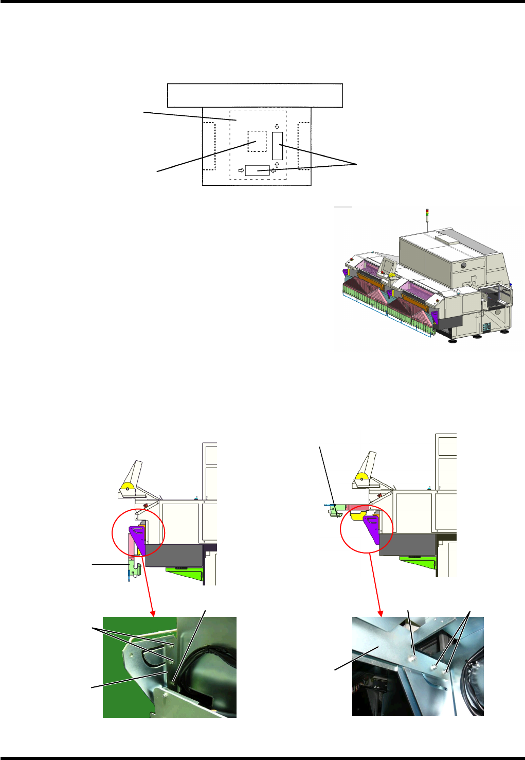
Setting guide plate
During transport, the guide plate of the machine is oriented in
vertical position as shown in Figure 1.
When installing the machine, take the following steps to change
its orientation to horizontal position (Figure 3):
1.
1. Remove the bolt 1 securing the bracket on the side of the
guide plate.
2. Loosen the bolt 2 securing the bracket on the side of the
guide plate.
3. Hold the guide plate guide and raise the top panel from the
position in Figure 2 to the one in Figure 3.
4. Reattach the bolt 1 to the bracket on the side of the guide
plate.
5. Secure the bolts 1 and 2 at the position where the guide plate is almost parallel with the installation floor.
(Tightening torque: 10N·m)
Figure 3
Bolt 1 Bolt 2
Guide plate
Guide plate
Figure 2
Bolt 2
Bolt 1
Guide plate
Guide plate
Part supply unit
Places where the spirit
level takes a seat
Loader
Unloader
Anvil unit
XY table base
Figure 1
RL131
MAINTENANCE MANUAL
3.1 Outline of Installation
DA8MEC-11-010-A0
3.1-4
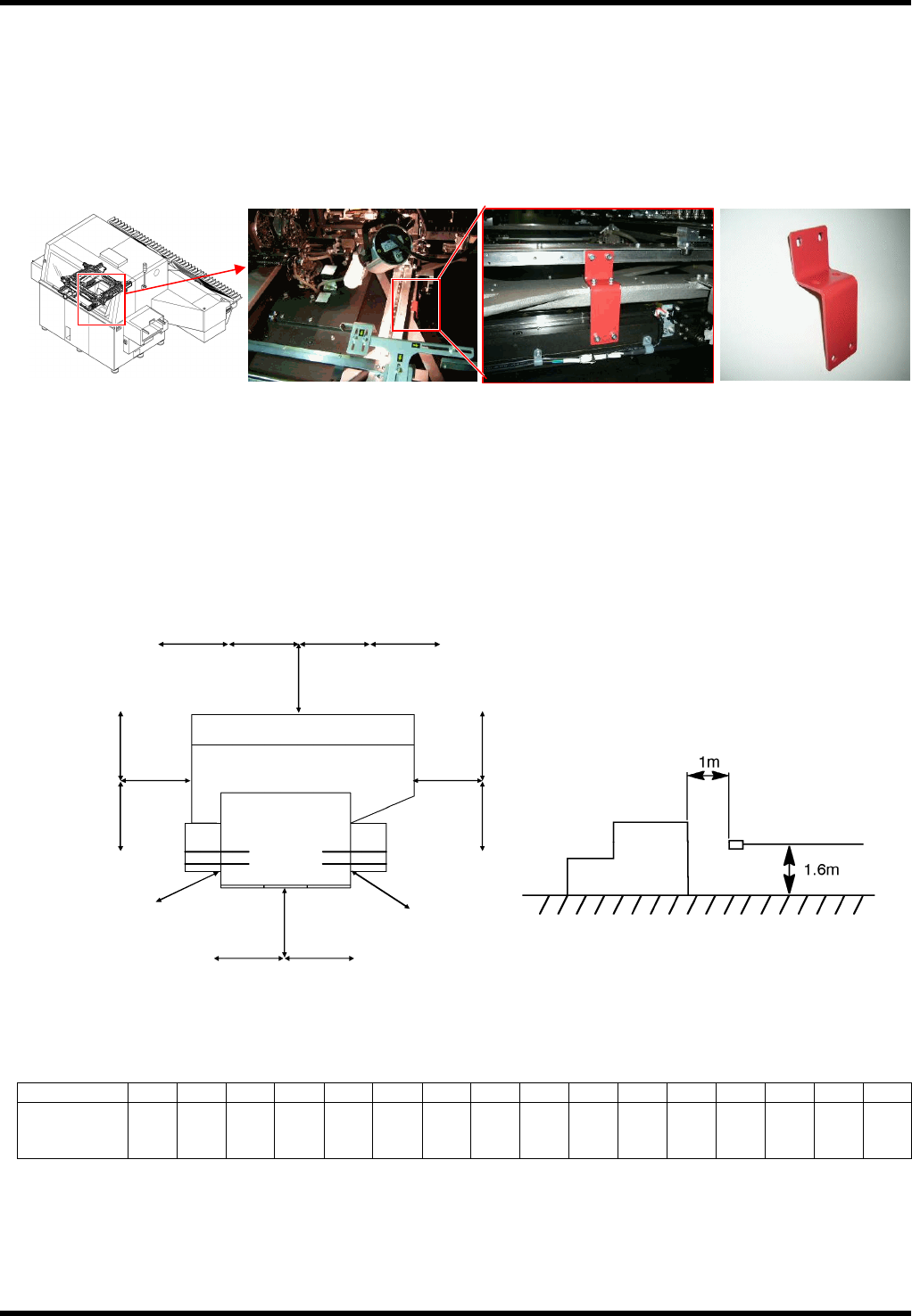
3.1.5 Removing Fixing Brackets (Red)
This machine is delivered with the X-Y table, Z axis and Z covers secured with the fixing brackets (Red) to
prevent them from moving during transport.
Before starting up the machine, remove all the fixing brackets in the photos below.
Store the removed fixing brackets.
1.
1. XY table unit
3.1.6 Noise Measurement
Here is the noise data of the machine measured at each point as shown below.
Measured Points
=REMARKS=
↔ : Distance 1 m each
Noise Data
Point A B C D E F G H I J K L M N O P
Measured
value
(dB (A) )
71.0 72.0 73.0 74.0 74.0 75.0 71.0 72.0 72.0 71.0 70.0 71.0 74.0 72.0 72.0 71.5
Dark noise: 29.5 dB (A)
Product No.: 108710403301 (x 1)
(Plane view) (Side view)
AB
C
D
E
F
GH I J K
L
M
N
O
P