Maintenance Manual.pdf - 第63页
RL131 MAINTENANCE MANUAL 3.2 Connectin g the Power Supply DA8MEC-11-020- A0 3.2-4 3.2.3 Setting Step-dow n Transformer Turn OFF the power switch of the distributio n panel. Connect U, V an d W to an appropriate term inal…
RL131
MAINTENANCE MANUAL
3.2 Connecting the Power Supply
DA8MEC-11-020-A0
3.2-3
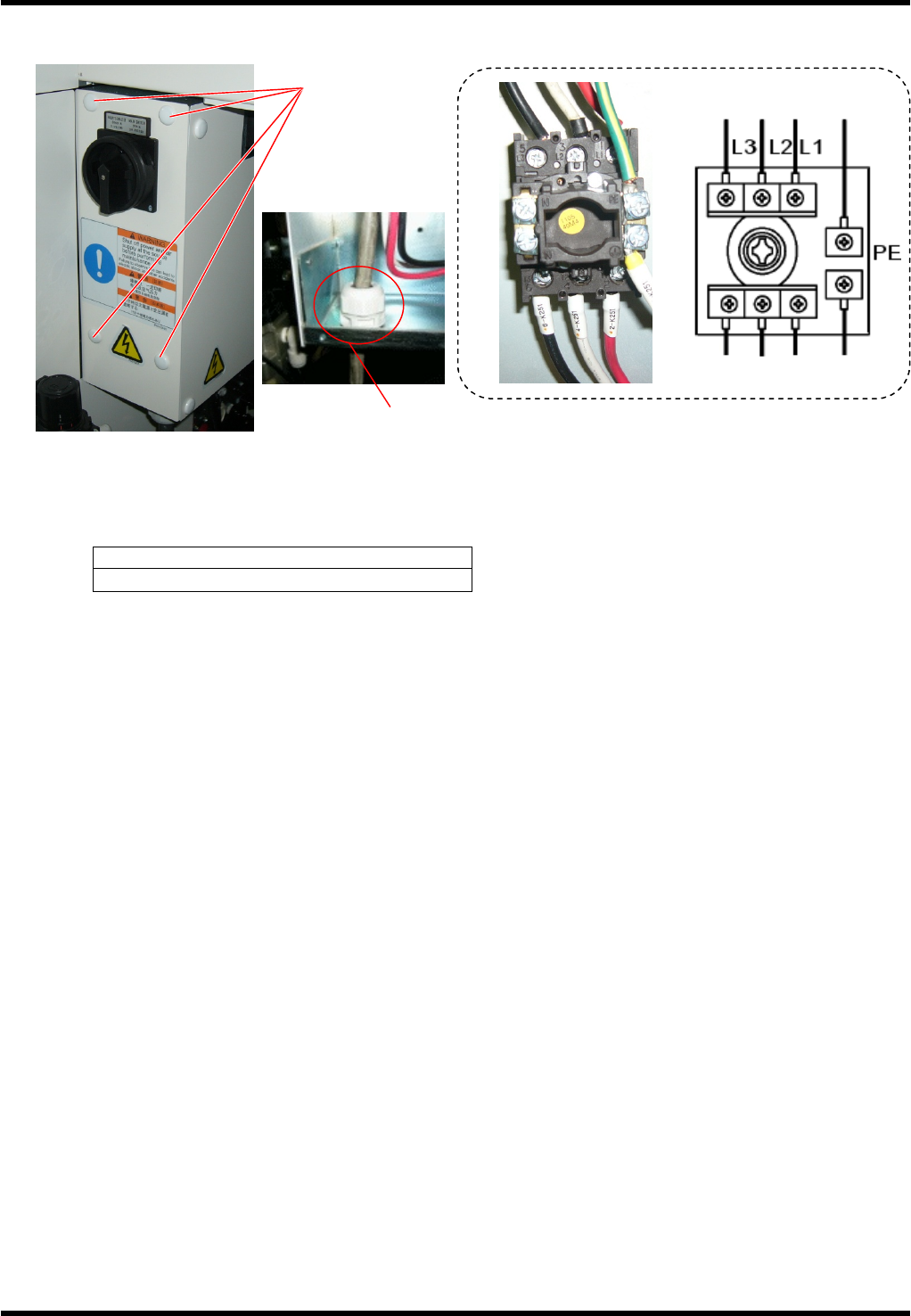
Connecting Cables
Turn OFF the power switch of the distribution panel.
Connect the distribution panel to the input terminals of the main switch by 3-core cable and one core
protective ground cable or 4-core cable (one for protective earth). The protective earth (PE) must be
connected.
Screw tightening torque
1.6 N×m
Fix the power cable securely with the cable gland (SC lock).
Check that the cable is not loosened under a tension of 100 N.
Inside of the machine
Factory power
Screw cramp x 4
Cable gland (SC lock)
RL131
MAINTENANCE MANUAL
3.2 Connecting the Power Supply
DA8MEC-11-020-A0
3.2-4
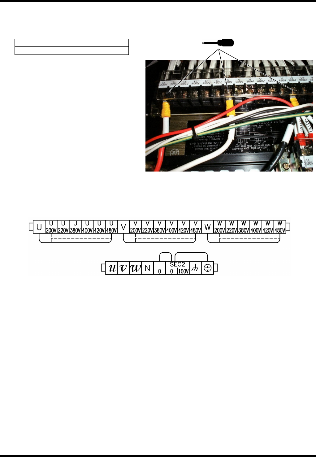
3.2.3 Setting Step-down Transformer
Turn OFF the power switch of the distribution panel.
Connect U, V and W to an appropriate terminal of the voltage respectively.
Screw tightening torque
2.5 N×m
Terminal layout
Output terminal
U, V, W: 3f200V
0, 100V: 1f100V
Input terminal
Select from 200 / 220 / 380
/ 400 / 420 / 480
RL131
MAINTENANCE MANUAL
3.2 Connecting the Power Supply
DA8MEC-11-020-A0
3.2-5
3.2.4 Checking Voltage
Using a tester, measure the voltage among the input and output terminals of the step-down transformer to
make sure the rated voltage is supplied.
1.
1. Turn OFF the breaker and circuit protector on the output side of the step-down transformer.
2. Turn ON the main switch.
3. Using a tester, measure the voltage between the input terminals of the step-down transformer to make
sure the rated voltage is supplied.
4. Measure the output terminals of the step-down transformer. Voltages between U and V, V and W, W and
U should be 200V AC.