00191017-01.pdf - 第168页
6 Product / Package Form User’s Manu al Line Computer UNIX 6.1 Package Form Editor Software Version 403.xx Edition 06/ 97 6 - 8 Depending u pon wheth er the curr ent packa ge form is a PDC, a regu lar or irr egular FDC, …

User’s Manual Line Computer UNIX 6 Product / Package Form
Software Version 403.xx Edition 06/97 6.1 Package Form Editor
6 - 7
6.1.2.1 SERVICES Menu
The SERVICES menu contains only one option with the following function:
-
Starting the Feeder Editor for the definition of the feeders which are to be used for feeding the
current component (package form).
●
Select menu item SERVICES --> Starting Feeder Editor.
The Feeder Editor is opened (see chapt. 9).
6.1.2.2 Setting Area of Package Form Editor
The appearance (layout) of the main window is set by activating the "Vision data" or "Handling data"
button. The <Name of package form type> button is used for a subsequent change of the package form type.
Setting possibilities for the display in the main window
-
Vision data This button is automatically activated by default when the Package Form
Editor is opened.
With this setting it is possible to edit the package form data that are
required for optical centering using the Vision System.
NOTE If the current package form is a standard package form
(numbers ranging from 1 ... 1499), the word "write-protected" is displayed
below the "Vision data" button. This means that none of the vision data
can be changed.
-
Handling data With this setting all specifications for the processing of the particular
component type are defined.
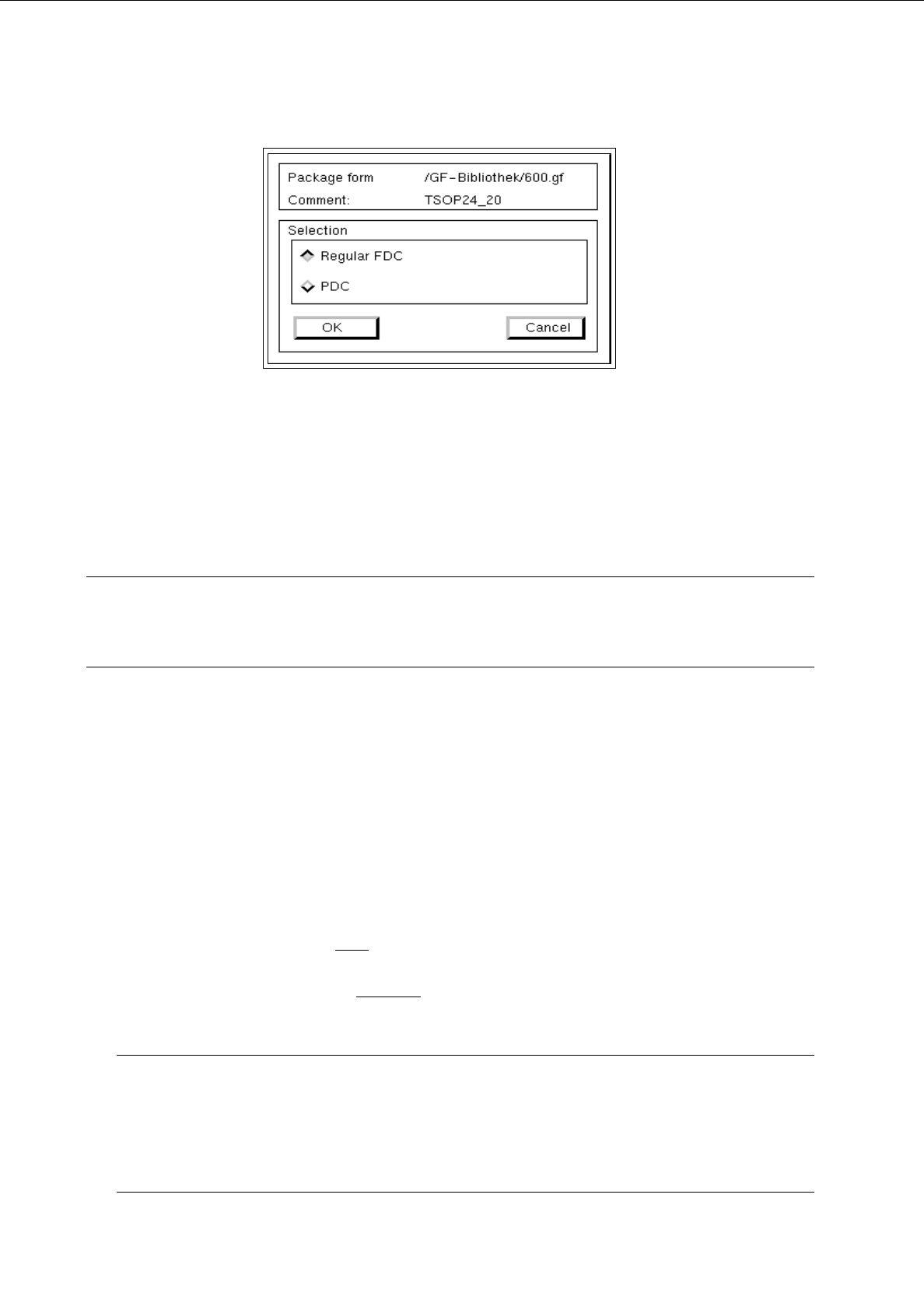
Changing the package form type
Once defined, FDCs and PDCs can still be changed into PDCs or FDCs, respectively. This is not possible
with BGA and standard package forms.
●
Click on (e.g.) <irregular FDC>.
The dialog box for the selection of the new package form type is opened.
6 Product / Package Form User’s Manual Line Computer UNIX
6.1 Package Form Editor Software Version 403.xx Edition 06/97
6 - 8
Depending upon whether the current package form is a PDC, a regular or irregular FDC, the following selection
possibilities for the new type are available:
-
A PDC can be converted into a regular or irregular FDC.
-
A regular FDC can be converted into an irregular FDC or a PDC.
-
An irregular FDC can be converted into a regular FDC or a PDC.
NOTE
If the package form type is to be changed from an FDC to a PDC, a warning message is displayed
informing you that all model and group data will be deleted.
6.1.2.3 Selection Field "Features" (PDC) - Setting "Vision data"
-
Cubic component
The characteristic of the current package form can be set by means of the "Cubic component" button.
By default, this button is automatically activated when the Package Form Editor is opened. This set-
ting means that the current package form is of cubic design (featuring a plane top) permitting the
vision system to expect clearly outlined borders.
The setting "Cubic component" must
be deactivated by clicking on the button whenever a cylindrical
package form is present.
If the component is to be picked up off-center
(in relation to the package form’s center) for subsequent
placement, the setting "Cubic component" must be deactivated as well.
NOTE
If the current package form is a standard package form, the setting under Properties cannot be chan-
ged since the button is inactive.
In the case of FDCs and BGAs the "Cubic component" button is contained in the "Acceptance limits"
editing area.
User’s Manual Line Computer UNIX 6 Product / Package Form
Software Version 403.xx Edition 06/97 6.1 Package Form Editor
6 - 9
6.1.2.4 Package Form Editor Command Area - Setting "Vision data"
NOTE
The command area is not displayed if the current package form is of the "PDC" type (see Fig. 6.1.2).
In the command area (see Fig. 6.1.1) only the "Create" command can initially be selected. The remaining
commands cannot be activated until an already-created pin or grid group is selected from the view area.
COMMANDS
The procedures for executing the commands are described in the following.
-
Create
A new pin group (see section 6.1.3.2) or a new grid group (see section 6.1.3.3) can be created.
●
Click on Create.
The window for the description of the new pin or grid group is opened (see Fig. 6.1.16 and
Fig. 6.1.21).
-
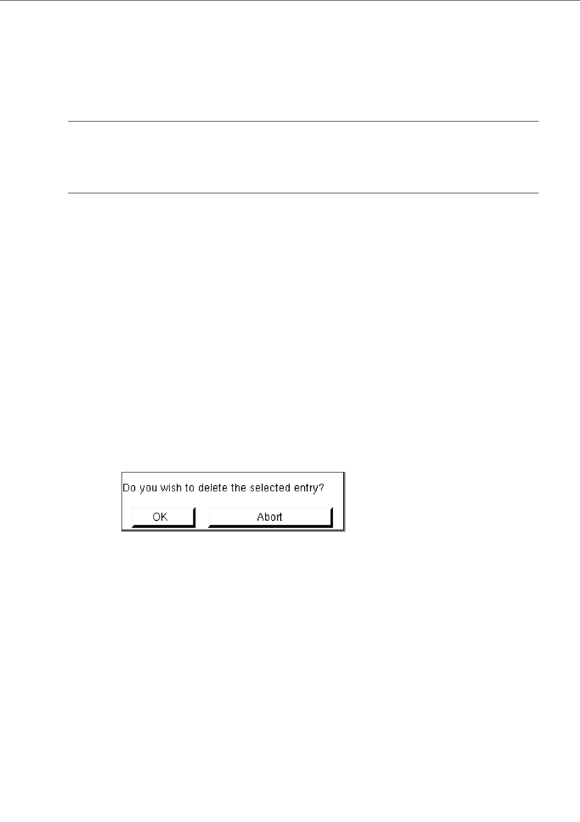
Delete
A selected pin or grid group can be deleted.
●
In the display area, select any pin or ball of the group you wish to delete. The selected group is
displayed, surrounded by a rectangle.
●
Click on Delete.
The following dialog box is opened.
●
Click on OK in the dialog box.
The dialog box is closed. The group is no longer displayed in the display area.
-
Group
This command permits the window for the description of the group data for a selected object (pin
group/grid group) to be opened.
●
From the view area select the group whose group data you wish to edit.
The selected group is surrounded by a rectangle.
●
Click on Group.
The window for the description of the group data is displayed on the screen (see Fig. 6.1.16 or
Fig. 6.1.21).