00191017-01.pdf - 第339页
User’s Manual Line Computer UNIX 12 Production Tools / S tation and Line Configuration Software Version 403.xx Edition 06/97 12.1 Configuration Editor 12 - 5 The mai n window i s subdivi ded as fol lows: - Display area (…
12 Production Tools / Station and Line Configuration User’s Manual Line Computer UNIX
12.1 Configuration Editor Software Version 403.xx Edition 06/97
12 - 4
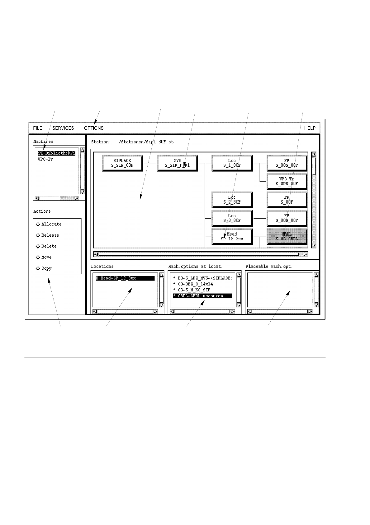
12.1.2 Main Window of Configuration Editor (Structure Editor)
In the Structure Editor the maximum permitted configuration of the selected machine type is shown.
Fig. 12.1.1 Structure Editor (Machine Type "SIPLACE 80F)
menu bar
selected
machine option
command area
selection field
"Locations"
selection field
"Mach. options at locat."
selection field
"Placeable mach. opt."
selection field
"Machines"
location /
machine option
"Head"
location
display area

User’s Manual Line Computer UNIX 12 Production Tools / Station and Line Configuration
Software Version 403.xx Edition 06/97 12.1 Configuration Editor
12 - 5
The main window is subdivided as follows:
-
Display area (for description refer to section 12.1.2.1)
-
Selection fields (for description refer to section 12.1.2.2)
-
Menu bar The menu bar contains the "FILE", "SERVICES", "OPTIONS" and
"HELP" menus.
The "FILE" menu is described in
section 12.1.2.3
, the "SERVICES" menu
in
section 12.1.2.4
.
The "°Component changeover table" menu option of the "OPTIONS"
menu is described in section 12.1.2.5.
NOTE
Since the functions and operation of the "OPTIONS" and "HELP" menus are similar to those in other
application programs of the line computer, they are described comprehensively in chapt. 2.
-
Command area (for description see section 12.1.2.6)
12.1.2.1 Display Area of Structure Editor
In the display area of the Structure Editor the maximum possible configuration of the machine type is displayed
as a structure.
-
Each rectangle within the structure represents a machine option type.
-
The machine option types are factory-defined. The original data of a machine option were defined in a
machine option type.
-
A given machine option type can be the location for lower-level machine option types. These lower-
level machine option types are connected to the higher-level machine option type by means of lines.
-
The topmost machine option type in the display area is the station. It is the location for lower-level
machine option types.
-
Upon starting the Structure Editor the rectangle of the topmost machine option type is selected.
If another rectangle is clicked on, the displays in the selection fields change (see section 12.1.2.2).
-
By double-clicking on the rectangle of a machine option type, the same becomes a machine option,
which is, however, not part of the machine yet.
12.1.2.2 Selection Fields of Structure Editor
For the machine options of a location to be displayed in the appropriate selection field, the location
(rectangle) must first be selected in the display area by clicking the mouse button.
Selection Fields "Locations", "Mach. options at locat.", "Placeable mach. opt.":
These three selection fields are located in the main window of the Structure Editor (see Fig. 12.1.1) below the
display area. They are used for the selection of machine option s on which actions such as allocating, releasing,
deleting, moving or copying are to be performed (see section 12.1.2.6).

12 Production Tools / Station and Line Configuration User’s Manual Line Computer UNIX
12.1 Configuration Editor Software Version 403.xx Edition 06/97
12 - 6
NOTE
The following explanations apply if no command is currently activated in the command area.
-
Locations
A machine option has been selected in the display area.
The next higher machine option is considered as the location and is displayed on the listing under
"Locations".
If a different machine option is selected in the display area, the next higher machine option is again
displayed as the location. Always the first entry on the list is selected by default (highlighted in dark).
Example: If the CRDL Tester is allocated to the placement head and if the rectangle "CRDL"
has been selected in the display area, the "Head~SP_12_3xx" will be indicated as
location for the CRDL Tester (see Fig. 12.1.1).
The list of locations can be empty if no locations exist. This is the case when a new station has been
created for which no station configuration has been created yet.
Each entry in the selection field "Locations" is marked by any one of the three letters "B", "U" or "T".
These letters have the following meaning:
B
Machine option is part of the machine
U
Machine option is not part of the machine
i.e., the machine option is not (yet) integrated in the structure of the machine.
T
Machine option partial structure is not (yet) part of the machine
i.e., the machine option partial structure is not integrated in the structure of the
machine. (A machine option partial structure can be, for example, the head onto
which the centering unit, the PCB centering unit and the CRDL Tester are positioned).
-
Machine option at Location
A location (entry) has been selected in the selection field.
All machine options allocated to this location are displayed on the listing "Mach. options at locat.".
If another location is selected, the machine options allocated to this location will be listed.
Example: If the turret head "Head~SP_12_3xx" is displayed under "Locations", the CRDL Tester
"CRDL~CRDL measurem." appears under "Mach. options at locat." if the CRDL Tester
was allocated to the head (see Fig. 12.1.1).
-
Placeable mach. opt.
A location has been selected in the display area.
NOTE
"Placeable machine options" are machine options that are positioned away from the machine thus not
forming part of the machine yet.