00191017-01.pdf - 第182页
6 Product / Package Form User’s Manu al Line Computer UNIX 6.1 Package Form Editor Software Version 403.xx Edition 06/ 97 6 - 22 - SST n umber "11 " Flip-chip camera SIPLA CE 80F3/F 4 Componen t dimen sion 20 x…

User’s Manual Line Computer UNIX 6 Product / Package Form
Software Version 403.xx Edition 06/97 6.1 Package Form Editor
6 - 21
General data on the sensor system types (SST) available
-
SST number "2"
Component camera HS-180
Component dimension (small contact area) 43 x 43 mm
Component dimension (large contact area) 50 x 50 mm
Camera’s field of view 35 x 35 mm
Resolution 74
µ
m/pixel
Minimum pin pitch 0.4 mm
-
SST number "3"
Coplanarity Module HS-180
-
SST number "6"
RV camera SIPLACE 80S-15/F3
Component dimension 14 x 14 mm
Camera’s field of view 18 x 18 mm
Resolution 54
µ
m
Minimum pin pitch 0,5 mm
Camera illumination 2 programmable illumination levels
-
SST number "7"
IC camera SIPLACE 80F3/F
4
Component dimension 55 x 55 mm
Camera’s field of view 38 x 38 mm
Resolution 74
µ
m
Minimum pin pitch 0,4 mm
Camera illumination 3 programmable illumination levels
-
SST number "8"
Coplanarity Module SIPLACE 80F3/F
4
-
SST number "9"
RV camera SIPLACE 80S-15/F3
Component dimension 14 x 18 mm
Camera’s field of view 19 x 25 mm
Resolution 54
µ
m
Minimum pin pitch 0,5 mm
Camera illumination 2 programmable illumination levels

6 Product / Package Form User’s Manual Line Computer UNIX
6.1 Package Form Editor Software Version 403.xx Edition 06/97
6 - 22
-
SST number "11"
Flip-chip camera SIPLACE 80F3/F
4
Component dimension 20 x 20 mm
Camera’s field of view 12,2 x 9,2 mm
Resolution 20
µ
m
Minimum pin pitch 0,2 mm
Minimum ball radius of BGA’s 0,04 mm
Camera illumination 3 programmable illumination levels
-
SST number "12"
RV camera (12-nozzle head) SIPLACE 80S-20/F
4
Component dimension 18 x 18 mm
Camera’s field of view 24 x 24 mm
Resolution 50
µ
m
Minimum pin pitch 0,5 mm
Minimum ball radius of BGA’s 0,2 - 0,25mm
Camera illumination 3 programmable illumination levels
-
SST number "13"
RV camera (6-nozzle head) SIPLACE 80F
4
Component dimension 32 x 32 mm
Camera’s field of view 39 x 39 mm
Resolution 81
µ
m/pixel
Minimum pin pitch 0,5 mm
Minimum ball radius of BGA’s ca. 200
µ
m
Camera illumination 2 programmable illumination levels
User’s Manual Line Computer UNIX 6 Product / Package Form
Software Version 403.xx Edition 06/97 6.1 Package Form Editor
6 - 23
6.1.2.9 Package Form Editor Editing Fields - "Handling data" Display
Editing field "Handling values"
-
Placing force Here, as a preset value for the force, a value between 1 and 10
is to be entered, which is then converted into the actual place-
ment force (see Table below).
The setting of the force that is used to place the nozzle on the
component and the component on the board depends on the
following parameters:
Material of the component package
Component size
Composition (consistency) of the adhesive or solder paste
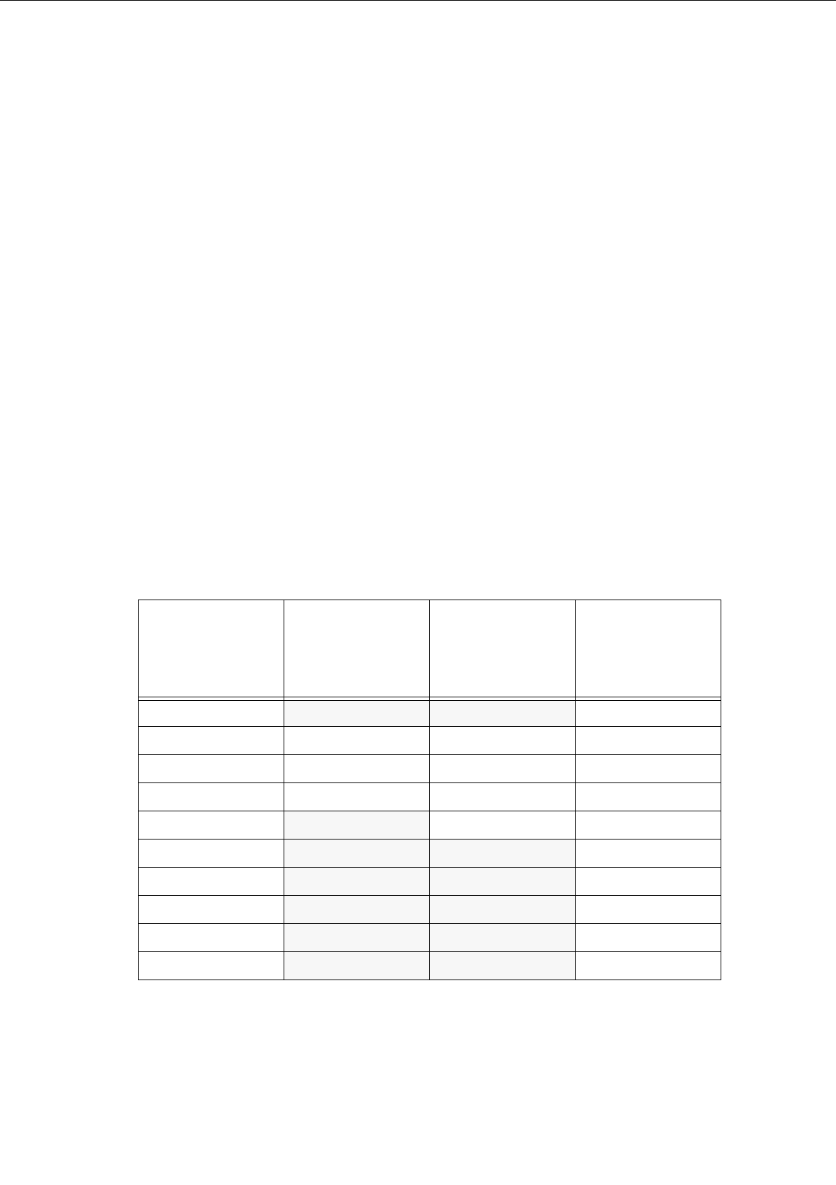
The Table below shows the conversion of the value entered (force presetting) into the value of actual
placement force appropriate for the respective placement head type and the nozzles used.
If the preset value lies, however, below or above the acceptable force setting range, the minimum or
maximum placement force, respectively, will be used for the head type in question (see the shaded
cells).
Value entered
[
N]
(force presetting)
Actual placement
force
[
N]
for
revolver head
with 3xx or 6xx type
nozzles
Actual placement
force
[
N]
for
revolver head
with 7xx type
nozzles
Actual placement
force
[
N]
for
IC-head with 4xx
type nozzle
1
2,4 2,4 1,3
22,42,42
3333
4444
5
455
6
4 56
7
4 57
8 4 58
9
4 59
10
4 510
Tab. 6.1 - 1 Placement Forces