00191017-01.pdf - 第499页
User ’s Manual Line Computer UNIX 17.1 I ntroduction Software V ers ion 403.xx Edition 06/97 17 - 1 Using thr ee PCBs as an ex ample , this ch apter co ntains a d escripti on of all wo rk step s requi red - from the ge- …

User’s Manual Line Computer UNIX
Software Version 403.xx Edition 06/97
17 - II
User’s Manual Line Computer UNIX 17.1 Introduction
Software Version 403.xx Edition 06/97
17 - 1
Using three PCBs as an example, this chapter contains a description of all work steps required - from the ge-
neration of the placement programs through to job scheduling.
This chapter can be used as a beginner´s guide for the new operator and be worked through step-by-step, or
it can serve as a reference or a refresher section for experienced programmers. All this is accomplished by the
two-page concept with the left side containing only keywords and the right side describing each work step in
detail.
The chapter is intended as a supplement to the other chapters of the User´s Manual and therefore cannot an-
ticipate every possible circumstance that may be of interest. For further information about a topic or a function,
please refer to the corresponding chapter in the User´s Manual.
In addition, it is very helpful to use the On-Line Help systems available:
—
On-line Bubble-Help:
contains information about all editing fields, icons and window areas.
• Click on the
Online Help On/Off
option on the
HELP
menu.
• Move the mouse pointer to the location where you wish to obtain explanations.
A window containing the Help information is opened and closed again by moving the mouse pointer.
—
Help Index:
contains a description on how to proceed concerning almost all topics.
• Click on the
Index
option on the
HELP
menu.
The Help Index is opened.
• Search for a topic using the
Text search
function, or browse through the contents and descriptions on
the topics by clicking on the terms highlighted in green.
The PCBs described relate to different learning objectives:
• PCB 1: single circuit, with focus on the basic principle of the generation of placement programs;
• PCB 2: single circuit, with focus on the description of customer-specific package forms;
• PCB 3: complex circuit, with focus on cluster technique.
All examples are based on a given line and station configuration. Since the configuration differs from customer
to customer, the data given can be used as an example only and must be adapted by the customers to satisfy
their individual requirements.
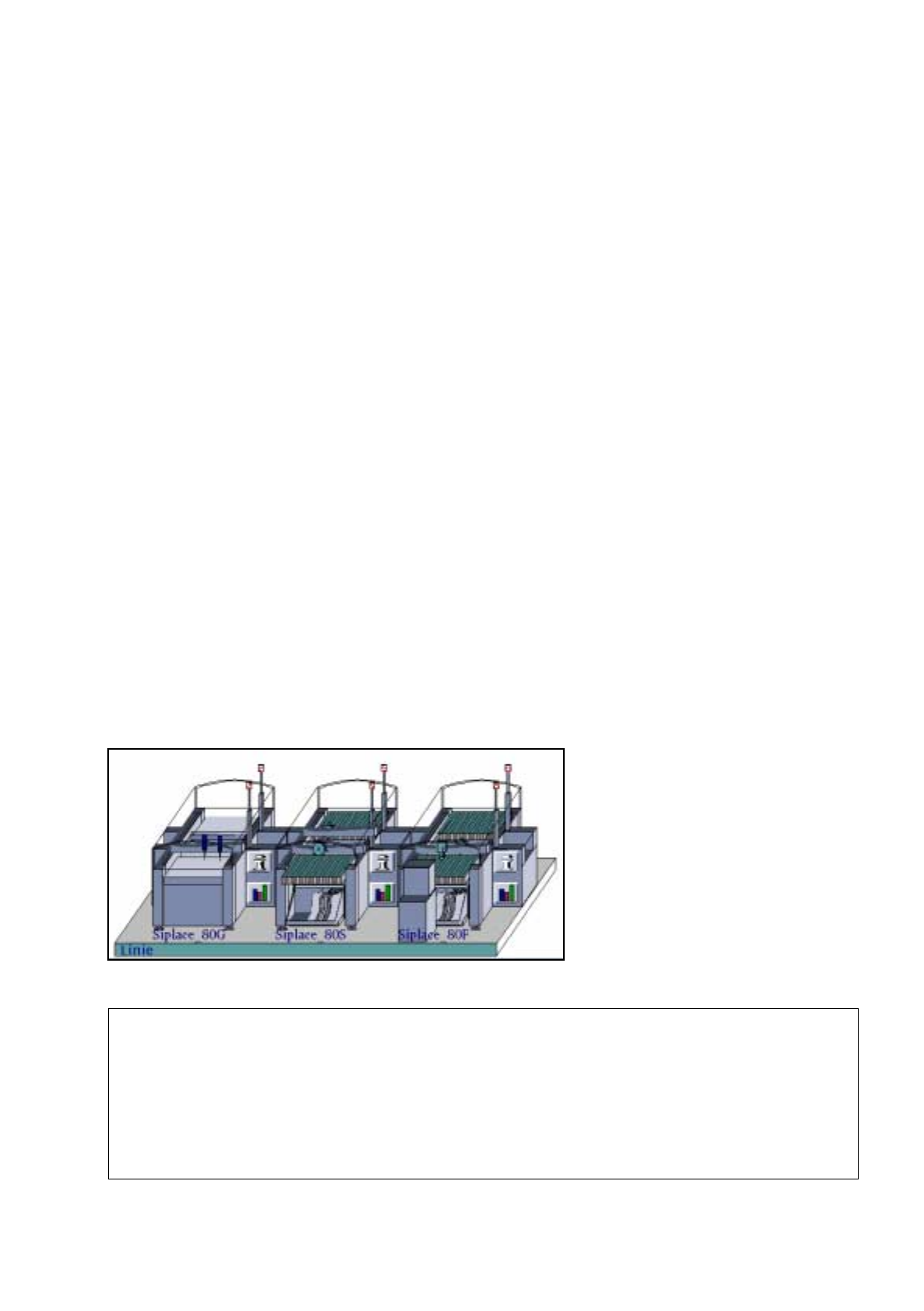
Station Configuration
17. Practical Tips on Using the LC UNIX
17.1 Introduction
Siplace_80G :
• optical PCB centering
Siplace_80S:
• optical PCB centering
• revolver head
• segment type 2 -> 6xx nozzles
• component camera 19x25 in head
-> sensor type 9
Siplace_80F:
• optical PCB centering
• IC-head -> 4xx nozzles
• IC-head camera -> sensor type 7
• revolver head
• segment type 2 -> 6xx nozzles
• component camera 19x25 in head
-> sensor type 9
• Waffle-Pack Changer
Line Configuration
17.2 From the Placement Program to the Assembly User’s Manual Line Computer UNIX
17.2.1 Overview Software Version 403.xx Edition 06/97
17 - 2
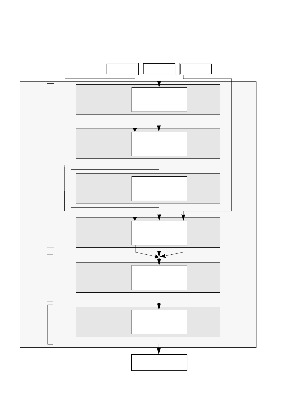
17.2 From the Placement Program to the Assembly
17.2.1 Overview
Set-up generation
Section 17.2.6
Line Control
Section 17.2.7
Component
description
Section 17.2.3
Package form (GF)
description
Section 17.2.2
PCB
description
Section 17.2.5
Adhesive pattern
description
Section 17.2.4
PCB 1 PCB 3
Assembly
Creation of a placement program
Generation of a
Scheduling a job
Package Form Editor
Desktop
Component Editor
Adhesive Pattern
Editor
PCB Editor
Optimization dialog
Job Control
PCB 2
set-up