00191017-01.pdf - 第178页
6 Product / Package Form User’s Manu al Line Computer UNIX 6.1 Package Form Editor Software Version 403.xx Edition 06/ 97 6 - 18 6.1.2.8 P ackage Form Editor Command Area - "Handling data" Displa y In the com m…

User’s Manual Line Computer UNIX 6 Product / Package Form
Software Version 403.xx Edition 06/97 6.1 Package Form Editor
6 - 17
- External Centering
The component is centered externally by means of appropriate
centering devices of an HS-180, or by means of the IC camera
or flip-chip camera of a SIPLACE 80F3/F
4
optical The component is centered by means of the optical centering
station of an HS-180, or by means of the IC camera or flip-chip
camera of a SIPLACE 80F3/F
4
.
mechanical The component is centered using the mechanical centering
station. (function is not currently used)
Rotate before centering The component is turned into placement position prior to being
measured (centered) by means of the optical centering station of
an HS-180 or the IC camera of a SIPLACE 80F3/F
4
(by 90°, 180° or 270°)
Selection field "Reduced acceleration"
When the setting "Special handling" is activated in the selection field you can reduce the speed at which the
placement head moves when performing pick-up, centering or placement operations along the x, y, z and
d-axes. It is thus possible to handle and and place also large components (e.g. PLCC's 84) securely.
- Special handling
"Special handling" is defined for the pick-up, centering and
placement cycles of a component.
Z during pick-up reduced acceleration of the z-axis of the RV or IC head
on picking up the component from the pick-up position
X during centering reduced acceleration of the X-axis during transporting the
component from the camera to the placement position by means
of the IC head
Y during centering reduced acceleration of the Y-axis during transporting the
component from the camera to the placement position by means
of the IC head
D during centering reduced acceleration of the dp1- and dp2-axes of the RV head
and of the d-axis of the IC head upon centering the component
X during placement reduced acceleration of the X-axis during transporting the
component from the pick-up to the placement position by means
of the RV head
reduced acceleration of the X-axis during transporting the
component from the IC camera to the placement position by
means of the IC head
Y during placement reduced acceleration of the Y-axis during transporting the
component from the pick-up to the placement position by means
of the RV head
reduced acceleration of the Y-axis during transporting the
component from the IC camera to the placement position by
means of the IC head
6 Product / Package Form User’s Manual Line Computer UNIX
6.1 Package Form Editor Software Version 403.xx Edition 06/97
6 - 18
6.1.2.8 Package Form Editor Command Area - "Handling data" Display
In the command area (see Fig. 6.1.4) two different tools can be selected from (nozzle or sensor type) that can
be created or deleted by means of the corresponding commands. The desired tool type desired is selected by
clicking on the button adjacent to its name.
COMMANDS
The procedures to be followed for the execution of the commands are described in the following.
-
Create
This command can be used to create the nozzles and sensor system types required for the current
package form.
●
Activate the button of the desired tool type.
●
Click on Create.
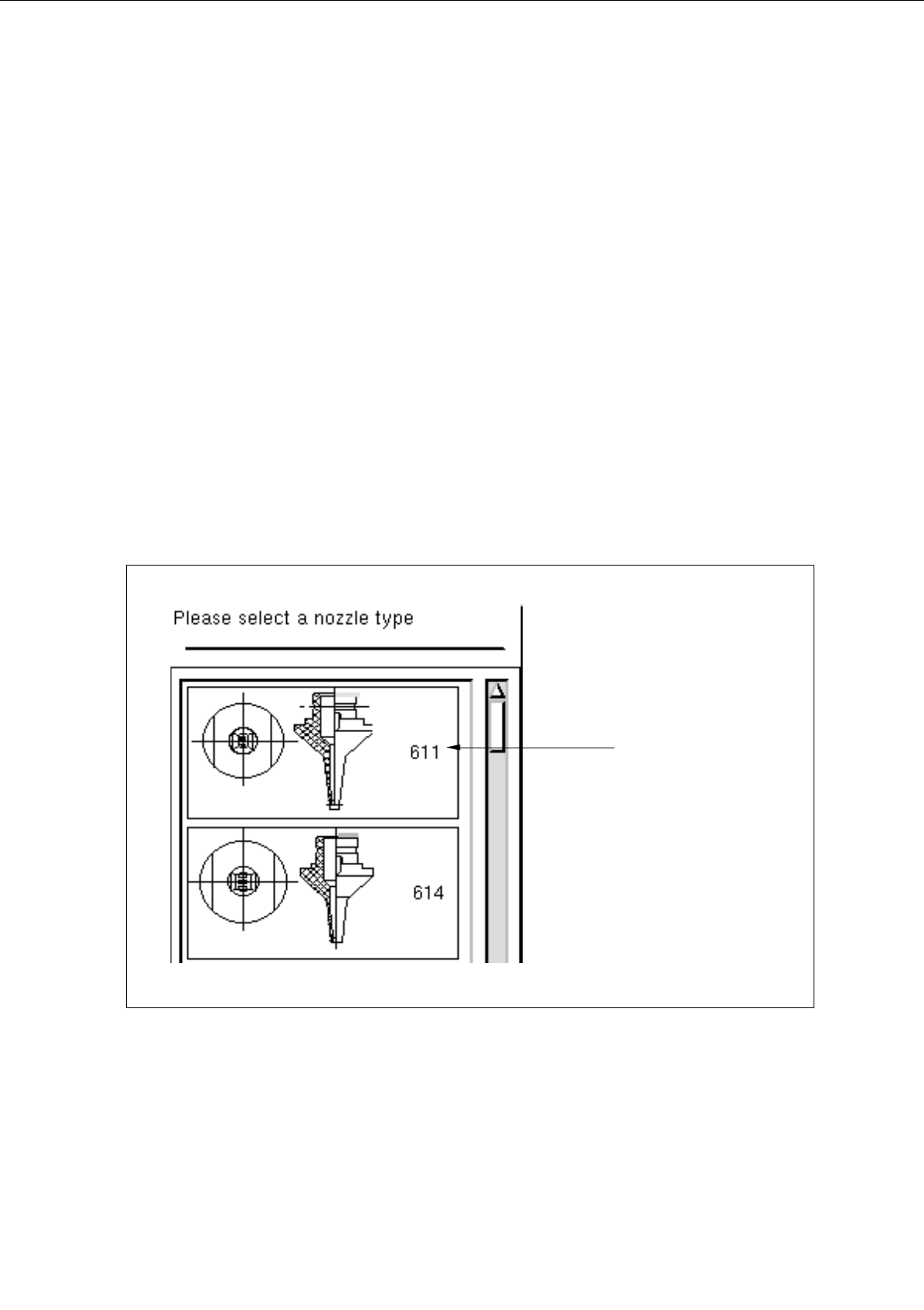
The selection window containing a list of all defined types of the selected tool type is opened.
Fig. 6.1.6 Selection Window of the "Nozzle Type"
nozzle type
User’s Manual Line Computer UNIX 6 Product / Package Form
Software Version 403.xx Edition 06/97 6.1 Package Form Editor
6 - 19
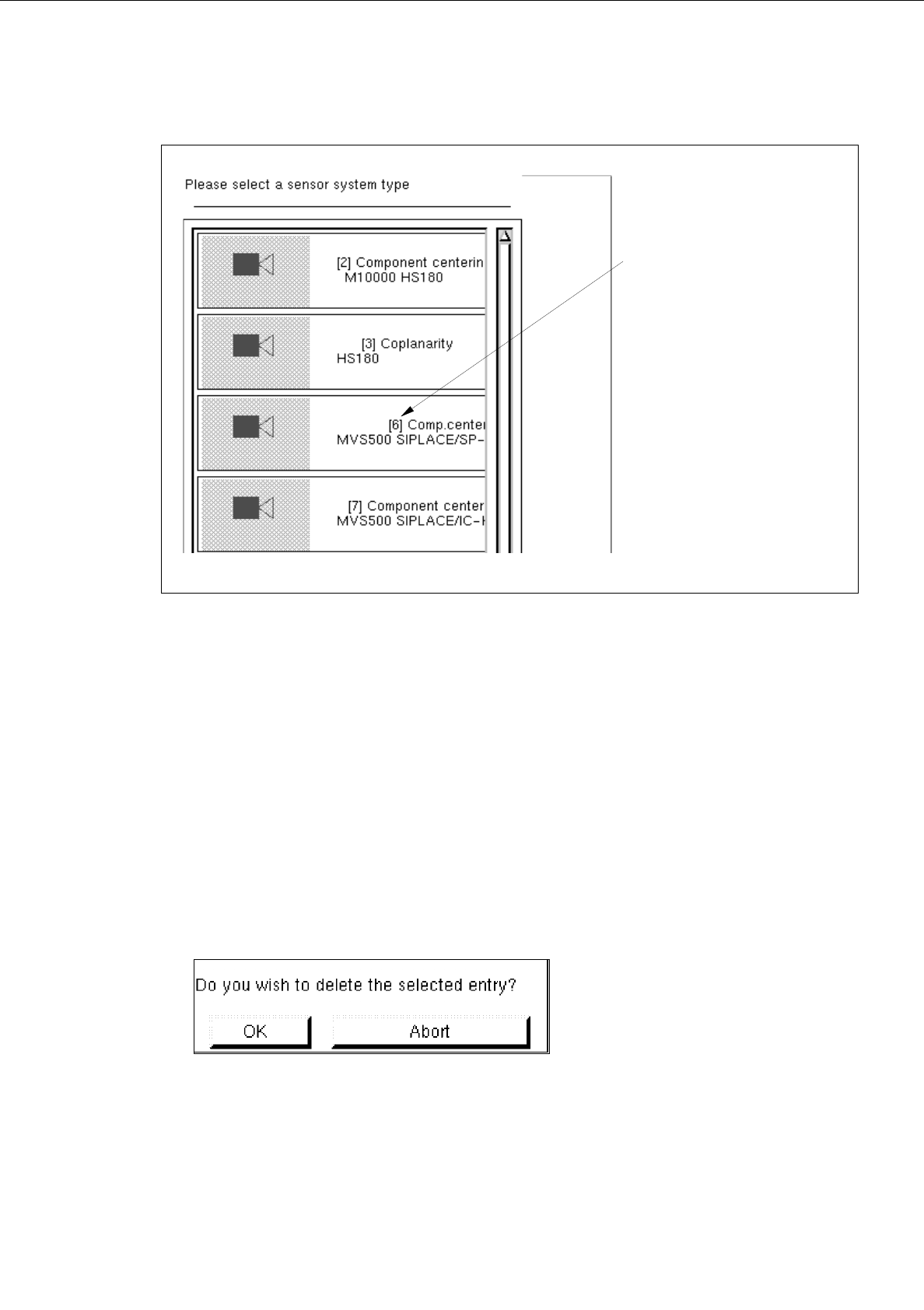
Fig. 6.1.7 Selection Window of the "Sensor Type"
●
Click on desired type.
The selection window is closed. The symbol of the selected tool type together with the number of
the created tool type is displayed in the display area of the main window.
-
Deleting
An existing tool can be deleted.
●
Click on button of the desired tool type.
All existing tools of the selected type are displayed.
●
Select tool from the display area.
●
Click on
Delete
.
The following dialog box is opened.
●
Click on
OK
in the dialog box.
The dialog box is closed.
The symbol of the selected tool is no longer displayed in the display area.
number of the
sensor system type