00191017-01.pdf - 第438页
14 Control / Control Modules User’s Manual Line Computer UNIX 14.4 Station Controll ers Software Version 403.xx Edition 06/97 14 - 38 Another field with in the c ommand a rea of the contr oller's mai n display windo…
User’s Manual Line Computer UNIX 14 Control / Control Modules
Software Version 403.xx Edition 06/97 14.4 Station Controllers
14 - 37
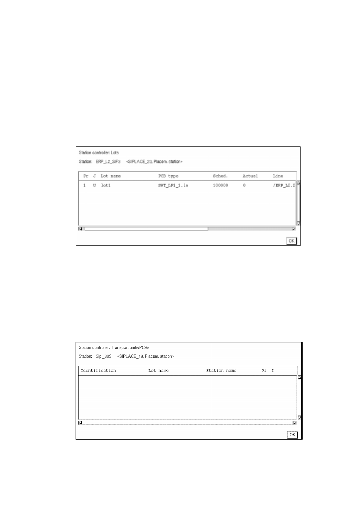
14.4.4.2 Command Area
Here, a listing of the scheduled lots and a listing of the scheduled PCBs with details on the current status of
the station can be called up, as required. The listings are shown in separate windows. The contents of the
windows are automatically and constantly updated as long as one of these windows is open.
-
Viewing Lot list
●
Click on Scheduled lots listed under "Display".
The window containing a listing of the scheduled lots is opened.
The job currently being processed is identified by an "a" in the first column.
-
Closing the window (lot list)
●
Click on Quit.
The window is closed.
-
Viewing PCB list
●
Click on Scheduled PCBs listed under "Display".
The window containing a listing of the currently processed (scheduled) PCBs is opened.
-
Closing the window (PCB list)
●
Click on Quit.
The window is closed.

14 Control / Control Modules User’s Manual Line Computer UNIX
14.4 Station Controllers Software Version 403.xx Edition 06/97
14 - 38
Another field within the command area of the controller's main display window is "Quit".
-
Closing
the Main Display Window
●
Click on
Quit
.
All currently open windows of the station controller's user interface are now closed
(see also "Quit" on the menu).

User’s Manual Line Computer UNIX 14 Control / Control Modules
Software Version 403.xx Edition 06/97 14.5 Set-Up Modification Generator
14 - 39
14.5 Set-Up Modification Generator
The principal task of the Set-Up Modification Generator is the display of set-ups, the creation of changeover
instructions and the creation of follow-up set-ups required in the production of given PCB types.
An SMD production line uses a sequence of different set-ups in the assembly of PCBs. The set-up data required
are held in the master data storage. The actual physical changeover procedure is carried out by the operator.
The user interface of the Set-up Modification Generator provides the required displays of set-ups and
changeover instructions (see Fig. 14.5.2), or else these can be output to the printer.
A request for set-up changeover can be initiated as follows:
-
by the station controller, for the particular station it controls, at the moment changeover is actually to
be performed at the station.
-
by the operator via the user interface of the Set-up Modification Generator, for the entire line, at any
time.
-
by the Data Manager for the entire line, at any time.
14.5.1 Terms Used in the Connection With Set-Ups (Set-Up Types)
• Initial Set-Up
This refers to the set-up from which the changeover procedure originates.
In the case of changeover requests released by the station controller or the Data Manager the initial
set-up is always the current set-up of the station or the line.
• Follow-Up Set-Up
This refers to the set-up of a line or a station that is to be the result of the changeover procedure. The
follow-up set-up can be a set-up already existing or one to be newly created by the Set-Up Modification
Generator for the production of a specific PCB type.
• Target Set-Up
This is an existing set-up for a given PCB.
When a follow-up set-up for this PCB type is to be created, the target set-up specifies where the
components are to be set up that are not contained in the initial set-up. All components required for the
production of the PCB type must be contained in the target set-up.
• Changeover Instructions
They describe the changeover from an intitial set-up to a follow-up set-up.